Checking and setting
44
2
3
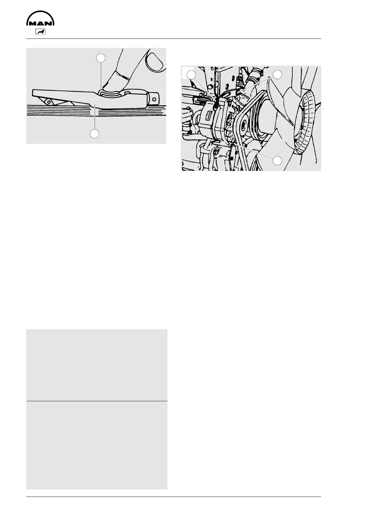
D Slowly depress pad  until the spring
can be heard to disengage. This will
cause the indicator to move upwards
If pressure is maintained after the spring
has disengaged a false reading will be ob-
tained!
Reading of tension
D Read of the tensioning force of the belt
at the point where the top surface of
the indicator arm À intersects with the
scale
D Before taking readings make ensure
that the indicator arm remains in its
position
Tensioning forces according to
the kg graduation on the tes-
ter
Drive
belt
New installation
When
width
Installa-
tion
After 10
min. run-
ning time
serv
c
ng
after
long run-
ning time
9.5 45–50 40–45 30
10.0 45–50 35–40 30
12.5 50–55 45–50 35
13.0 50–55 40–45 35
20.0 75 70 60
22.0 75 70 60
2/3VX 90–100 70–80 60
3/3VX 135–150 105–120 90
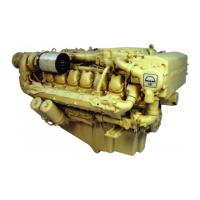
Tension and / or replace V-belts
1
1
2
Water pump - Alternator
D Remove fixing bolts À
D Remove lock-nut Á
D Swing alternator outwards until V-belts
have correct tensions
D Retighten lock-nut and fixing bolts
To replace the V-belts loosen lock-nut and
swing alternator inwards.