Technical information
26
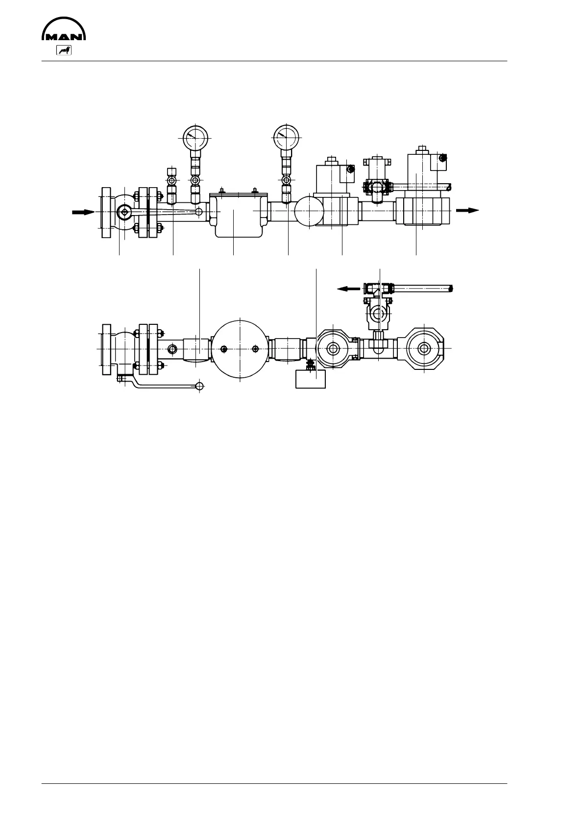
Notes on necessary gas plant components upstream of the zero pressure regula-
tor
1 23 4 56 7 8 9
1888
1 Ball cock
2 Push button cock
3 Pressure gauge with push button cock
4 Gas filter
5 Pressure gauge with push button cock
6 Gas pressure monitor
7 Safety solenoid valve
8 Leak gas solenoid valve
9 Main gas solenoid valve
Gas lock consisting of
D main and safety solenoid valve ( 9 and 7)
(de-energized to close)
D leak gas solenoid valves (only if required)
D leak gas pipe between zero pressure regulator and connection behind leak gas sole-
noid valve (at request)
Gas pressure monitor (6) for minimum gas pressure 10 mbar.
Gas pressure gauge (2 and 5) with push button cock. Indication up to 100 mbar
Hand ball cock (1) flanged type
Vent cock (2) push-button type
Gas filter (4) cleaning efficiency better than 0.05 mm
Hand ball cock flanged type