Checking and setting
40
2340
10
1885
8
12
9
11
71
4
2
6
3
5
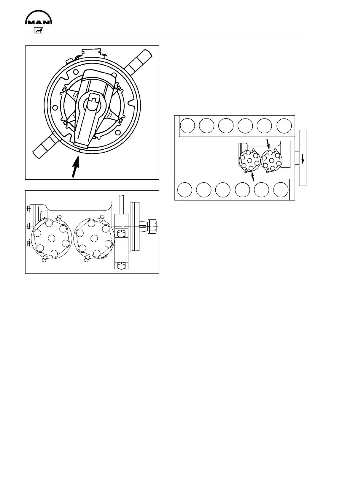
In this position of the distributor shaft,
insert the distributor. Note the location of
the spring clips for the distributor cap and
the cable entry (see diagram).
Hold the rotor and turn the distributor
slightly as it is being inserted so that the
drive gears will mesh readly.
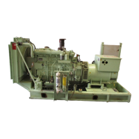
D Screw clamping lever to the bearing
housing
D Transfer the position of the groove in
the casing edge with paint or chalk to
the outside of the distributor housing so
that the ”cylinder No. 1” (cylinder No.
12) mark remains visible with the dis-
tributor cap in place. Install dust cover,
distributor rotor and cap
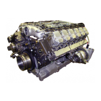
D Insert ignition cables. The paint mark
applied earlier will point to the cable
connection for cylinder No. 1 (cylinder
No. 12). Insert the other cables in the
sequence of the firing order shown in
the diagram
123456
789101112
1
5
3
6
2
4
11
9
12
8
10
7
1884
Set ignition timing by means of the strobo-
scope.
Adjusting the ignition timing
(by authorized specialist personnel)
The ignition timing should be checked
after every 2000 hours operation.
The adjustment or checking of the ignition
timing can only be made with the engine
running.
Check the engine timing by means of igni-
tion timing stroboscope. Marks for the
12° before TDC of cylinder No. 1 and
cylinder No. 12 are provided on a marking
disc on the front crankshaft end. A pointer
provides the mating mark.