Transmission of power by propshafts
35
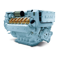
The working angle of a propeller shaft
The working angle ß of a propeller shaft is the
angle between the propeller shaft and the input /
output shaft.
Basic guidelines for installing propeller
shafts
When a single cardan joint, universal joint or ball
joint is rotated while bent, an irregular motion
occurs at the output end.
This irregular motion can be compensated for by
connecting two joints to one propeller shaft. For
the complete compensation of the irregular
motions, the following requirements must be met:
D Identical running angles at both joints (ß
1
=ß
2
)
D Both inner joint forks must lie in a plane
D Input and output shafts must also lie in one
plane
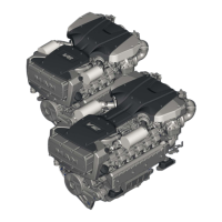
Propeller shaft arrangement in Z−Form
Propeller shaft arrangement in W−Form
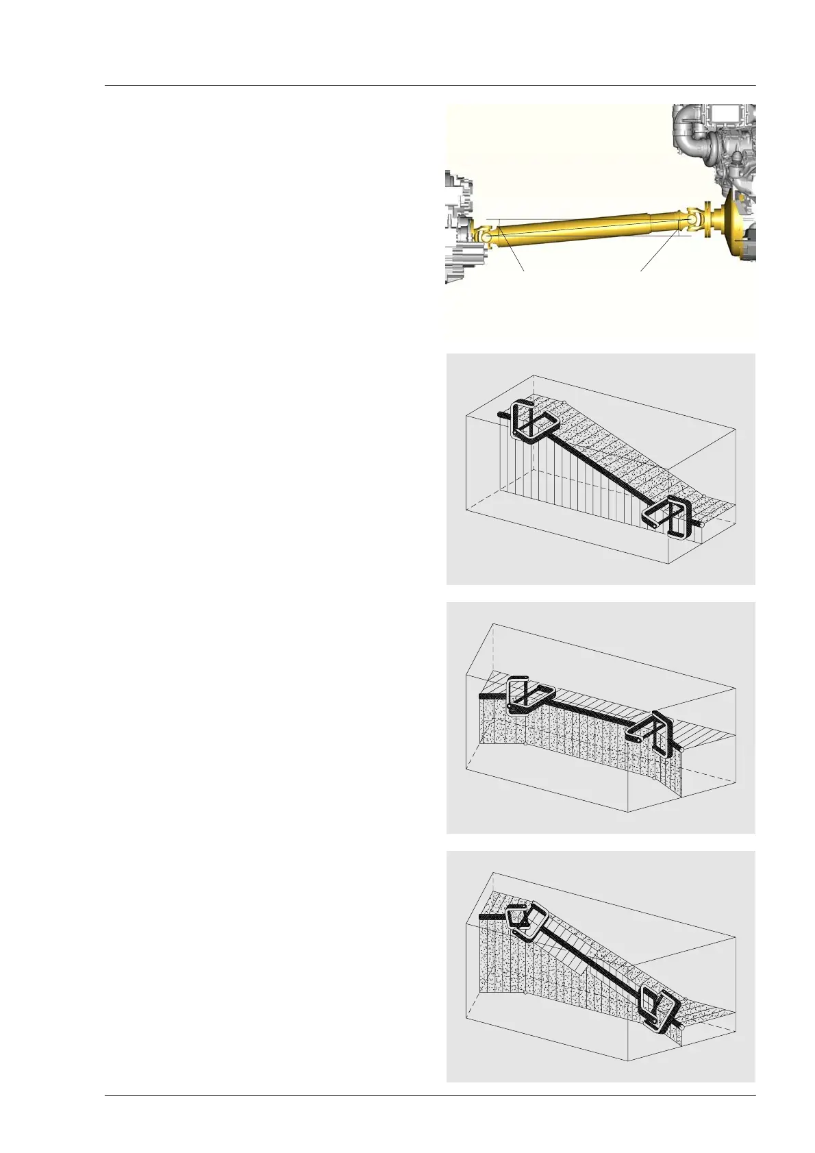
Exception:
In the case of a spatially−angled propeller shaft,
the input and output shafts do not lie in one plane.
To achieve a steady output motion, the inside
propeller shaft forks must be twisted against one
another so that they both lie within the angled
plane produced by their joints. In addition, the
spatial working angles must be the same.
b
2
b
1
 Loading...