Transmission of power by propshafts
36
Aligning engine and gearbox
Alignment type Permitted tolerances
1 Max. angle per joint See page 34
2 Input and output angles ß
1,
ß
2
(=working angles) must be the
same
Difference jß
1
−
ß
2
j 0.5°
3 Engine, propeller shaft and gearbox
must be arranged in a line in the
top view
<1 %o
i.e. over 500 mm measured length 0.5 mm
4 The inner fork heads must lie in a
plane
<1°
5 Static offset of engine to gearbox
longitudinal axis (in the plan view)
<1 mm
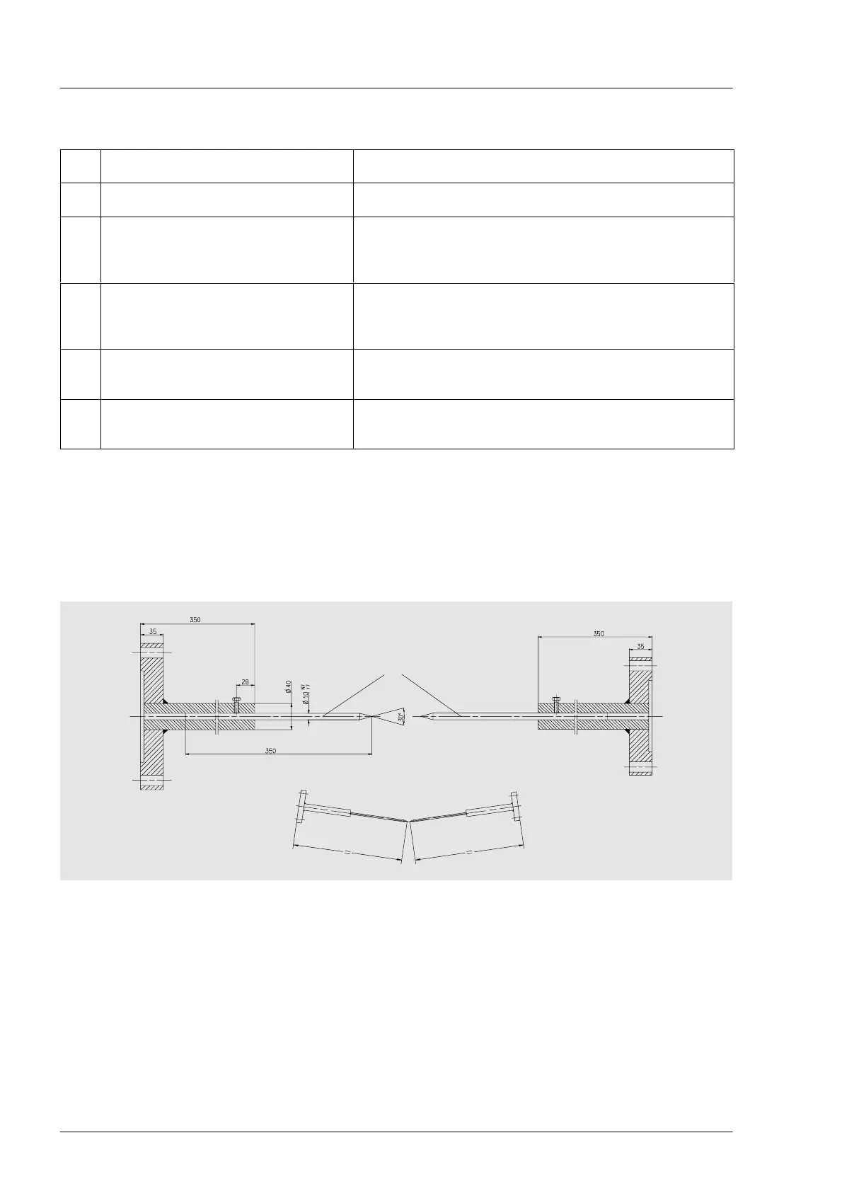
Auxiliary equipment consisting of two alignment rods can be used to obtain the same working angle for a
V-configuration.
Such auxiliary equipment is illustrated below.
For the dimensions given this equipment can be used for propeller shafts with lengths of
L
z
= 700 to 1300 mm. Shorter or longer propeller shafts require shorter or longer rods A.
A
Procedure: Mount alignment rods in place of the propeller shaft. Both parts must be of the same length.
Align engine or gear box so that the tips of the alignment rods meet. Remove the auxiliary equipment and
mount the propeller shafts.
 Loading...