18
8.4 Optional Accessory Connections
NOTICE
• Photo cells must be installed facing each other across the door's path within 6” (15 cm) of the plane of
the door and the beam no more than 5-3/4” (14,6 cm) above the floor.
• Keep low voltage wires separate from line voltage wires.
• Use copper conductors only.
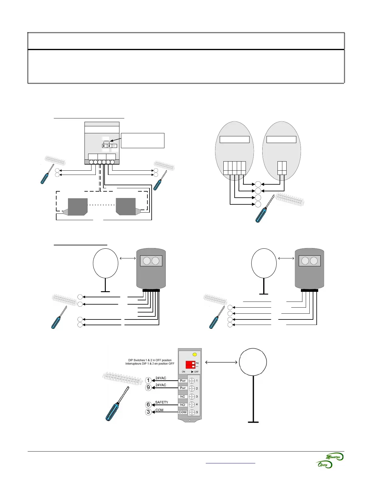
8.4.1 Electric Photo Cells / Photo Eyes (Non-Monitored)
Through Beam Type
Figure 25 - PHOTO 008
Figure 26 - PHOTO 015 / 016 / 045 / 050 / 051 / 059
Reflective Type
Figure 27 - PHOTO 018
Figure 28 - PHOTO 038
Figure 29 - PHOTO 060
For technical support, please call 1-800-361-2260 or visit www.manaras.com for more information
1
9
6
3
Always set the jumper located
inside the Interface Module on
N.O. (Normally Open)
ALIGNMENT
BLACK & WHITE
TRANSMITTER
RECEIVER
BLACK
TK-8200
Interface Module
POWER BEAM
RELAY
OUT
1 2 3 4 5 6
NO
NC
JMP
24VAC
24VAC
COM
SAFETY
BLACK & WHITE
BLACK
3
1
9
6
24VAC
COM
SAFETY
RX
42 3 51
Pwr
Com
NO
NC
Pwr
1 2
Pwr
Pwr
TX
24VAC
C1 [1]
3
1
9
SAFETY
COM
24VAC
24VAC
6
NO1 [2]
NC1 [3]
NC2 [4]
NO2 [5]
C2 [6]
P
P
BLUE
BROWN
ORANGE (COM)
BLACK (NO)
(NOT USED)
WHITE (NC)
3
1
9
SAFETY
COM
24VAC
24VAC
6