30
9.1 WIRING OF THE MGT OPERATOR
Do NOT connect any accessory controls until the limit switch adjustments have been completed and the operator
is functioning properly.
Refer to the electrical diagrams on pages 38 and 39 and to the accessory wiring diagrams on page 32 and 33.
WARNING
EXERCISE CAUTION WHEN OPERATING MACHINE. THE DRIVE CHAIN AND LIMIT CHAIN, WHEN
EXPOSED AND TURNING, COULD CAUSE SEVERE INJURY.
NOTE: Wiring diagrams are glued on the inside the control box cover. If the diagram is faded or damaged, call the
factory for a replacement. DO NOT INSTALL ANY WIRING OR ATTEMPT TO RUN THIS
OPERATOR WITHOUT CONSULTING THE WIRING DIAGRAM.
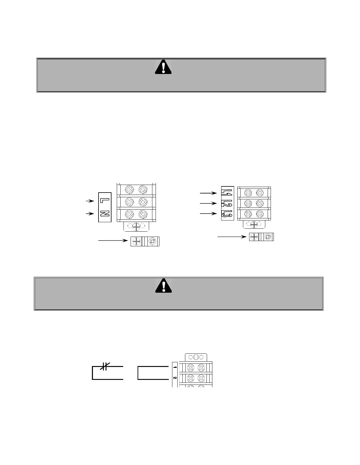
Main Power Supply
Power to the operator is of the permanent connection type. Connect according to local electrical code. Ground the
unit using the ground lug inside the control box.
• For single phase operators, connect the power supply to terminals L (line) and N (neutral) on the main
terminal strip.
• For three phase operators, connect the power supply to terminals L1, L2 and L3 on the main terminal strip.
Fi
ure 1
Power supply connection
WARNING
GROUND THE UNIT CORRECTLY USING THE COPPER GROUND LUG LOCATED INSIDE THE
OPERATOR CONTROL BOX.
NOTE: All other connections on the terminal strip (1 to 9) are low voltage class II 24 VAC.
1. External interlock between terminals 1 and 2. A jumper is factory installed between these two terminals. If
an external interlock is used (such as interlocking between two doors), remove the jumper between 1 and 2
and wire the interlock between these two terminals.
Fi
ure 2
External interlock
JumperInterlock Device With
Normall
Close
Three phase
power
supply
Single
phase power
supply
Ground
Ground
 Loading...