31
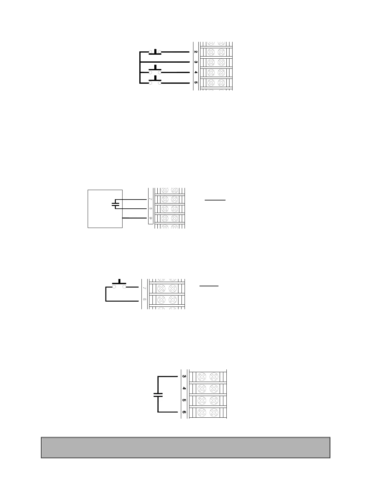
2. A 3 button push-button station (open/close/stop) can be wired to terminals 2, 3, 4 and 5. Two push-button
stations can be wired to these same terminals by following the wiring diagrams on pages 38 and 39.
Fi
ure 21 Three button push-button station
3. Three terminals are provided for the wiring of a radio-control receiver. Terminal #9 is Ground, #7 is 24 VAC
(common) and #8 is the relay contact provided by the radio-control receiver to activate the door to open or
close. Furthermore, terminals 7, 8 and 9 are doubly available on the terminal strip inside and on a separate
small terminal strip located on the side of the unit. This terminal makes it convenient to wire-up a standard
single button radio receiver on the side of the unit. When the transmitter is activated, the door will open to the
fully open position. From the fully open position, the door will close. If transmitter is activated while closing,
the door will reverse to the fully open position.
NOTE: It may be required to reverse connections to 7 and 9 for other types or radio receivers (Allstar, Linear,
Pulsar ...).
Receiver
Fi
ure 22 Radio-control
A single button open/close door device can be wired to terminals 7 and 8 to behave in the same way as the radio
control receiver.
Fi
ure 23 Single button device
NOTE: If several control devices are to be used, connect one and check for proper operation before connecting the
next device.
4. A reversing edge can be wired up to terminals 3 and 6. These terminals can also be used for any other
reversing devices such as loop detectors and photocells.
Fi
ure 2
Reversing edge or other device
IMPORTANT: Upon completion of all wiring connections, readjust limits as mentioned in section 4.4 using
"Open", "Close" and "Stop" buttons.
Stop
Open
Close
24 V a. c.
Contact
Ground
Normally open
contact
NOTE: (select B2)
Radio Control = B2 wiring
Momentary contact to open, close
and stop with a 3 buttons station.
NOTE: (select B2)
Open/Close = Radio Control
Momentary contact to open and close
with single button station.
 Loading...