www.mc-techgroup.com LA | 1.01.01 17
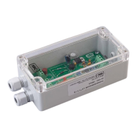
13.1.1 ELECTRONIC CONTROLLER LA1.1
The following steps must be carried out for electrical connection (see Figure 4):
• Loosen the 4 lid screws and remove the lid.
• Lead the connection cables through the respective clamp fitting.
• The electrical connection of the sensor LA1S or LA25S is made according the colors on the
terminals 5 = brown and 6 = white.
Old sensors of type LA1, LA25 and LA1-H are to be connected to terminals 5 = brown and 8 =
white. In this case, a bridge must be installed between terminals 6 and 7.
If the older sensor LA1, LA25 or LA1-H is connected the same way as the
new sensor LA1S, the function of the electronic is inverted: no liquid = alarm,
liquid = OK.
If a new sensor LA1S is connected the same way as the old sensor LA1, LA25
or LA1-H no line break control is existing.
• The voltage supply is connected to terminals 1 = L, 2 = N and 3 = PE.
• The alarms are connected to terminals 12, 22 = alarm.
• The center contact is connected to terminals 11, 21.
• The relay contact 14, 24 = OK is energized in the good state.


 To Next Page