National Crane 1-21-2019 Control # 104-07 9-5
1400A SERVICE MANUAL CRANE INSTALLATION
NOTE:
Gross Vehicle Weight Rating (GVWR) is
dependent on all components of the vehicle (axles,
tires, springs, frame, etc.) meeting the
manufacturers’ recommendations. Always specify
GVWR when purchasing trucks.
Diesel engines require a variable speed governor
and energize-to-run fuel solenoid for smooth crane
operation. Electronic fuel injection is also required.
All mounting data is based on a National Series
1400A with subbase and an 85 percent stability
factor.
The complete unit must be installed in accordance
with factory requirements, and a test performed to
determine actual stability and counterweight
requirements per SAE J765; contact the factory for
details.
Transmission neutral safety interlock switch is
required.
PTO REQUIREMENTS
Horsepower
The crane is equipped with a piston hydraulic pump that
supplies 132 LPM (35 GPM) to the hoist,132 LPM (35 GPM)
to the boom and telescope, and 61 LPM (16 GPM) to the
turn and outrigger circuit. The pump shaft needs to turn at
proper RPM as shown below to provide these flows. The
PTO torque rating need to be at least 542 N.m (400 lb-ft) or
63 kW (85 HP) per 1000 RPM of PTO shaft speed.
Direct PTO Mount
Most pump installations can be direct mounted to the PTO
using adapter assemblies available from the PTO supplier. If
the pump is direct mounted, its weight should be supported
by a strap between the pump and the transmission. The
splined shaft coupling in a direct mount pump installation
requires lubrication. A special multi-lube (#200S Silver
Streak) is applied to the shaft during original installation and
should be reapplied to the shaft the on PTO semi-annually
thereafter.
PTO Ratio
Pump shaft speed is determined by truck engine RPM and
PTO ratio:
Pump Shaft Speed = Truck Engine RPM x PTO Ratio
The following PTO ratio and engine speed combinations
provide proper pump shaft speed which is the recommended
maximum speed for the 1400A pump.
The speeds shown below are optimum operating speeds.
The engine must be operated at a speed such that the
horsepower developed is adequate to run the pump under
pressure and provide the required flow. Optimum speed for
the 1400A is 1900 RPM.
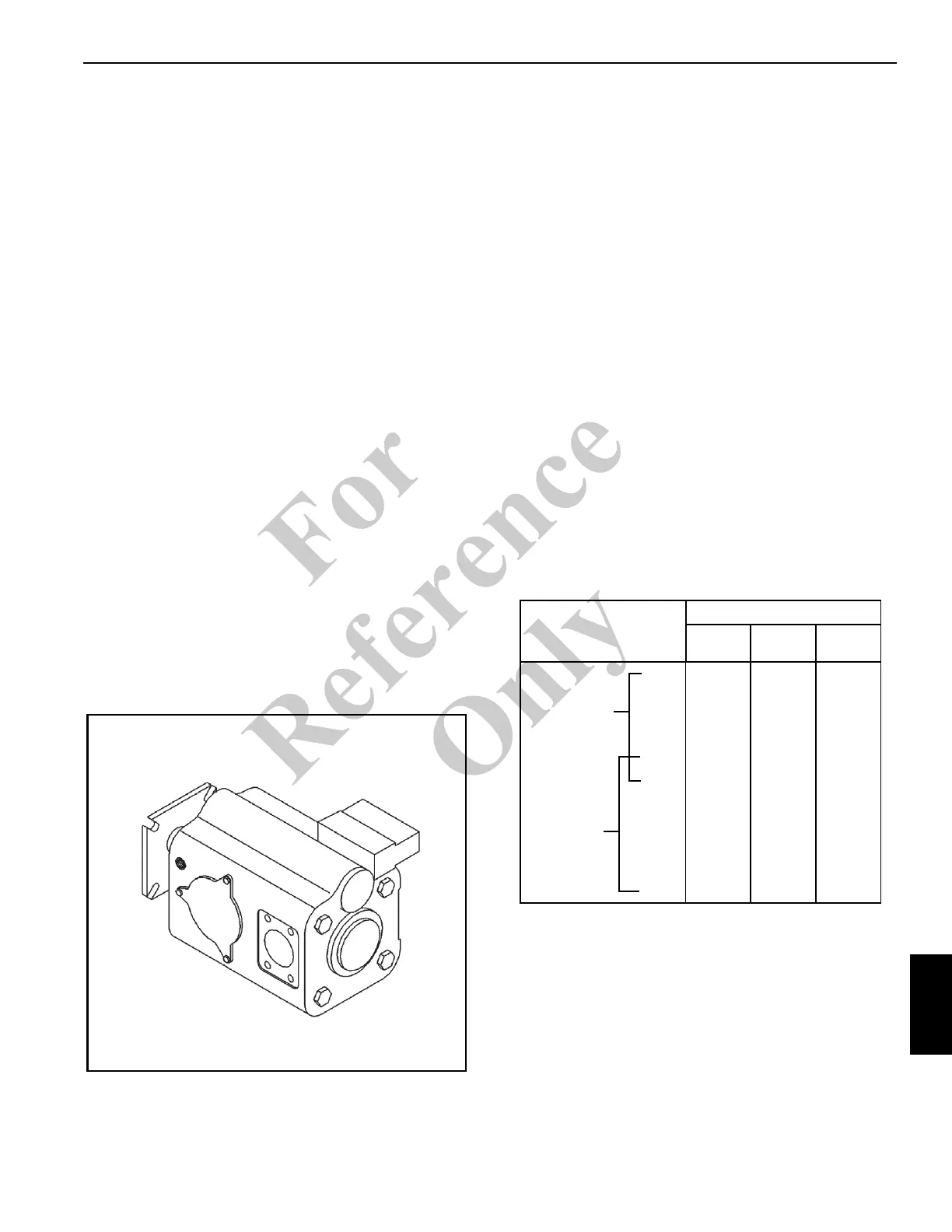
Pump Rotation
The hydraulic pump must be installed so that the pump
rotates the same direction as the arrow on the pump
housing. Make certain which direction the power take off
output shaft rotates before selecting a clockwise (CW) or
counter-clockwise (CCW) rotation hydraulic pump. Either
CW or CCW rotation pumps are available and are marked
clearly with a directional arrow on the pump housing.
ENGINE SPEED
(RPM)
PTO RATIO
1800 RPM
PUMP
2000 RPM
PUMP
2200 RPM
PUMP
2900 62% 69% 76%
2800 64% 71% 79%
2600 69% 77% 85%
2400 75% 83% 91%
2200 82% 91% 100%
2000 90% 100% 110%
1800 100% 111% 122%
1600 113% 125% 138%
1500 120% 133% 147%
1400 129% 143% 157%
Gasoline
Engine
Optimum
Speed
Range
Diesel
Engine
Optimum
Speed
Range
Fo
r
Reference
Only