CRANE INSTALLATION SERVICE MANUAL 1400A
9-4 1-21-2019 Control # 104-07
MOUNTING CONFIGURATION
The mounting configuration shown is based on an 85%
stability factor. The complete unit must be installed on the
truck in accordance with factory requirements and a test
performed to determine the actual stability and
counterweight requirements. If the bare truck weights are not
met, counterweight is required. A summary of mounting and
truck requirements is as follows:
• Working area 360°
• Gross Axle Weight Rating (GAWR) Front 9072 kg
(20,000 lb)
• Gross AxleWeight Rating (GAWR) Rear 15422 kg
(34,000 lb)
• Gross Vehicle Weight Rating 24 494 kg (54,000 lb)
• Wheelbase (WB) 655 cm (258 in)
• Cab to AxIe/Trunnion (CT) 457 cm (180 in) minimum
• After Frame (AF) 234 cm (92 in) minimum, 279 cm (110
in) preferred Frame Section Modulus (SM), front axle to
end of after frame: 759 MPa (110,000 psi) 492 cm
3
(30
in
3
). See “Truck Frame Strength” section.
• Estimated bare chassis weight required for stability prior
to installation of crane or accessories:
- Front* 4082 kg (9,000 lb)
- Rear* 3629 kg (8,000 lb)
• Maximum bare chassis weights to mount 30.5 m (100 ft)
or 33.5 m (110 ft) booms with 16.5 m (54 ft) of jib, cab
and continuous rotation, 379 L (100 gal) of fuel, 136 kg
(300 lb) of men to achieve a final mounted weight of 24
131 kg (53,200 lb):4355 kg (9,600 lb) front axle and
3765 kg (8,300 lb) rear axle.
• Maximum bare chassis weights to mount 38.7 m (127 ft)
boom with 9.1 m (30 ft) jib, cab and continuous rotation,
379 L (100 gal) fuel, 136 kg (300 lb) of men to achieve a
final mounted weight of 24131 kg (53,200 lb): 4128 kg
(9,100lb) front axle and 3,629 kg (8,000 lb) rear axle.
• Additional options (e.g. auxiliary hoist, man baskets,
etc.) or heavier bare chassis weights will require
additional axles or a GVWR in excess of 24,494 kg
(54,000 lb); in some states special permits for overload
are required.
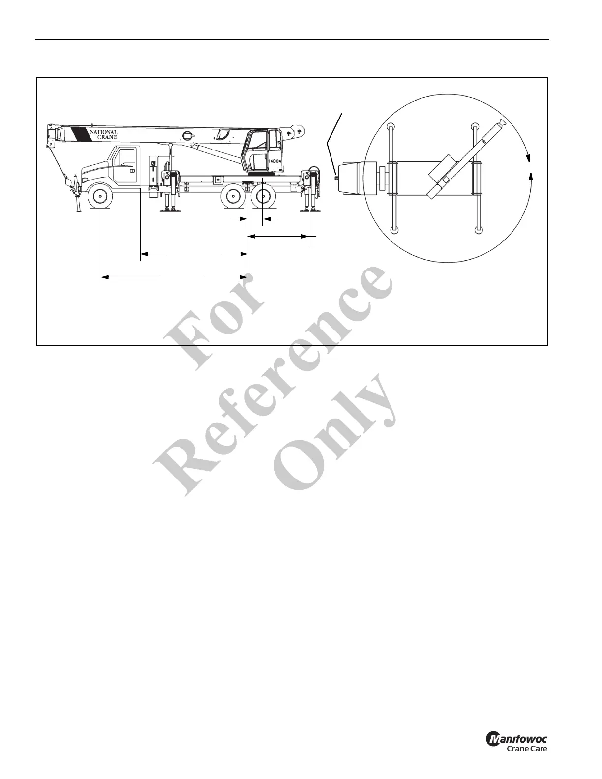
• The diagrams above show the 360° working area that
can be achieved with the single front outrigger (SFO)
(standard on the Series 1400A), The SFO is required
when extending the boom and lifting loads over the front
of the truck. See Truck Frame Strength on page 9-6 for
truck frame strength required for mounting crane and
SFO.
360°
Front Stabilizer
Required (SFO)
*Clear of obstructions (mufflers, exhaust stacks, ect.) on top
of the truck frame for a full 8 foot (2.44m) of width.
360° Full capacity working area
FIGURE 9-2
1400A Minimum Measurements
92" (233.6 cm)
258" (655 cm)
*
180
”
(457.2 cm)
20" (26" Typ)
50.8 cm (66 cm Typ)
Fo
r
Reference
Only