OUTRIGGERS SERVICE MANUAL1400A
7-6 1-21-2019 Control # 104-07
OUTRIGGER MONITORING SYSTEM (OMS)
(OPTIONAL—STANDARD IN NORTH
AMERICA)
The Outrigger Monitoring System (OMS) aids the operator in
accurately programming the Rated Capacity Limiter (RCL)
by automatically identifying the position of each outrigger
beam. The OMS uses four string potentiometers, one
potentiometer in each outrigger beam, to identify if an
outrigger beam is positioned to one of three predefined
locations, including fully retracted, mid-extend, and fully
extended.
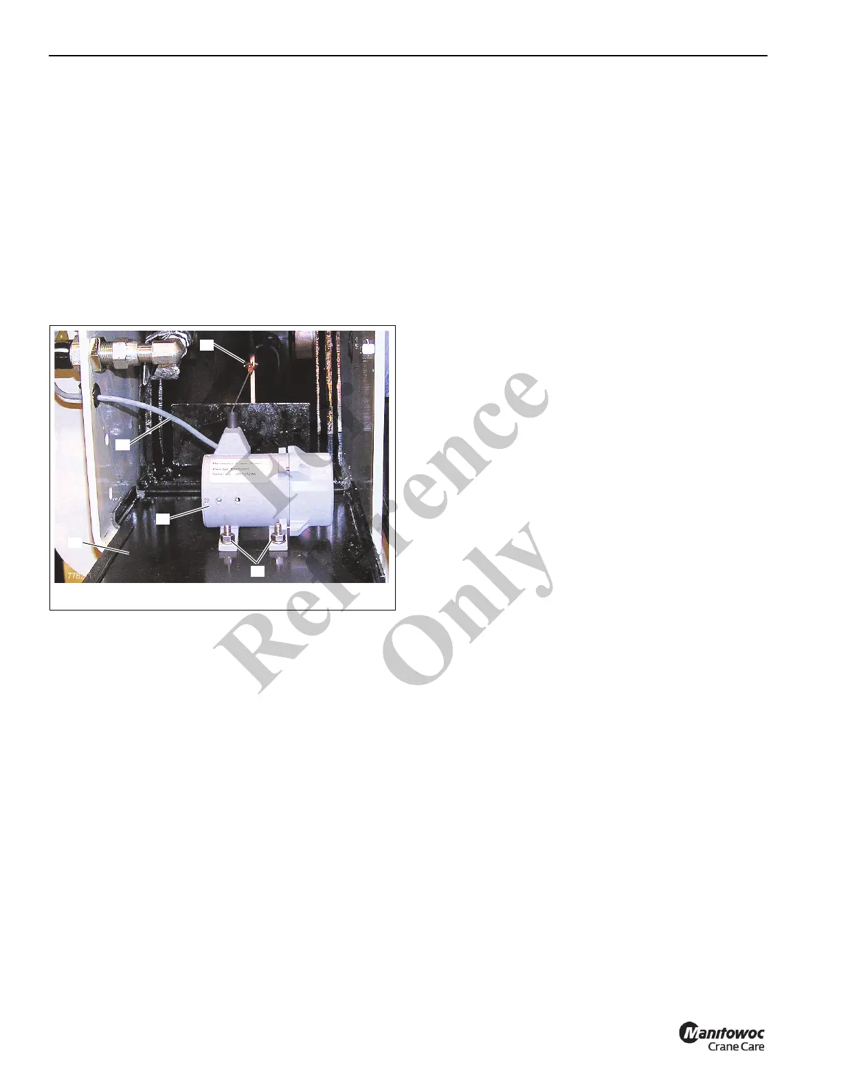
String Potentiometer
Remove
1. Fully retract outrigger beam.
2. Remove outrigger box cover (1, Figure 7-6).
3. Disconnect spring clip (2, Figure 7-6) from its attaching
point on outrigger beam.
4. Disconnect electrical connector (3, Figure 7-6) at string
potentiometer (4).
5. Remove the screws (5, Figure 7-6) securing string
potentiometer; remove string potentiometer.
Install
1. Fully retract outrigger.
2. Using screws (5, Figure 7-6), mount the string
potentiometer (4) to the outrigger box cover (1).
3. Connect electrical connector (3, Figure 7-6) to string
potentiometer (4).
4. Attach spring clip (2, Figure 7-6) to attaching point on
outrigger beam.
5. Mount outrigger box cover (1, Figure 7-6) on outrigger
box.
6. Calibrate string potentiometers; refer to Calibrate,
page 7-6
Calibrate
Calibrating the string potentiometer is done through the
crane's RCL. Refer to the Load Moment Indicator Operator's
Manual for detailed instructions.
Fo
r
Reference
Only