National Crane 1-21-2019 Control # 104-07 7-3
1400A SERVICE MANUAL OUTRIGGERS
Removal
1. Check that the stabilizer is fully retracted and the float
removed.
2. On the stabilizer end, tag and remove the top wear pads
and shims from the outrigger beam.
NOTE: The outrigger wear pads and shims are adjusted at
the factory. Tag the shims and wear pads during
removal to ensure proper reinstallation.
3. Extend the outrigger beam slightly so that a lifting strap
(Figure 7-4) can be attached to the outrigger beam.
NOTE: To prevent nick and gouges to the bottom of the
outrigger beam, do not attach chains to the
outrigger beam.
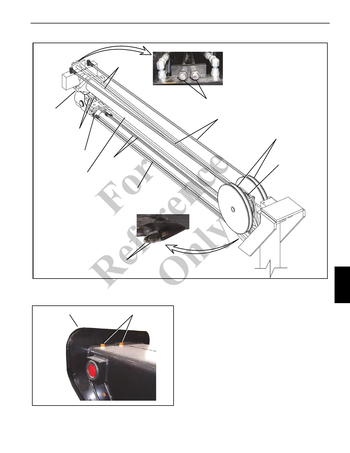
4. Remove the hydraulic lines from the base of the extend
cylinder (Figure 7-1).
FIGURE 7-2
Hydraulic Hose Reel
on the Nose of the
Extend Cylinder
Cable Sheaves on
the Nose of the
Extend Cylinder
Hydraulic Tubes to
Stabilizer Cylinder
Cable Sheaves
on 2
ND
Section
Hydraulic Hose
Hydraulic Hoses
Extend/Retract
Cables
Trunnion
Anchor Brackets
Top Cable Adjustment
Bottom Cable
Adjustment
Extend Cylinder
Wear Pad Bolts
Outrigger Box
FIGURE 7-3
Fo
r
Reference
Only