HYDRAULIC SYSTEM SERVICE MANUAL 1400A
2-16 1-21-2019 Control # 104-07
Outrigger Manifolds
The outrigger functions are controlled by two manifolds
located at the front and rear outrigger boxes. The front
manifold contains the extend/retract valve, front outrigger
component valves, and the optional front jack valve. The rear
outrigger manifold contains the rear outrigger component
valves. The valves are operated by solenoids that are
controlled by switches on the outrigger control boxes located
on the side of the truck bed. An optional hand held outrigger
control box can be installed in the crane cab.
Holding Valves
Pilot operated check valves located in the valve block on
each cylinder acts as holding valve to keep the cylinder from
collapse due to hose failure. Do not remove a valve block
unless the cylinder is completely retracted.
Do not try to repair or set the valve pressure. If a holding
valve is suspect, replace it with a new valve.
Swing Gearbox
The standard Glide Swing gearbox is locked in place by an
integrally mounted spring applied disc brake. The swing
brake switch located on the front console and is used to
activate the swing brake and park the turret in position. Press
the switch to activate the swing brake to keep the turret from
rotating. A red LED is illuminated when the swing brake
switch is applied.
The swing control lever can be used to slow and stop the
swing by moving the control lever to the opposite direction of
the swing. For example, if the lever is pushed forward for a
clockwise swing, pull the lever back to slow and stop the
swing.
Crane Function Power Switch
The crane function power switch in the crane cab energizes
a solenoid valve on the crane manifold located in the turret to
activate the controllers in the crane cab. The operator must
be in the operators seat for the crane function power switch
to be active.
HYDRAULIC PUMP
Description
The hydraulic system pressure is supplied by a axial piston
hydraulic pump mounted on the truck power take off (PTO).
The hydraulic piston pump requires a PTO rating of 75 hp
(55.9 kw) per 1000 RPM of shaft speed with 644 N.m (475
lb-ft) of torque.
Removal
If pump replacement is required, the hydraulic fluid should
also be replaced to avoid possible contamination.
1. Drain the hydraulic tank.
2. Tag and disconnect the hydraulic lines from the pump.
3. Remove the bolts from the pump rear mounting bracket.
4. Remove the bolts from the pump mounting flange and
slide the pump out of the PTO drive coupling.
Installation
1. Lubricate the splines on the pump and PTO drive shaft
coupling with heavy lithium grease.
2. Line up the splines on the PTO drive shaft coupling up
with the pump drive shaft and slide the pump drive shaft
into the coupling.
3. Bolt the pump to the PTO with the pump mounting
flange.
4. Bolt the pump rear mounting bracket to the truck
mounting bracket.
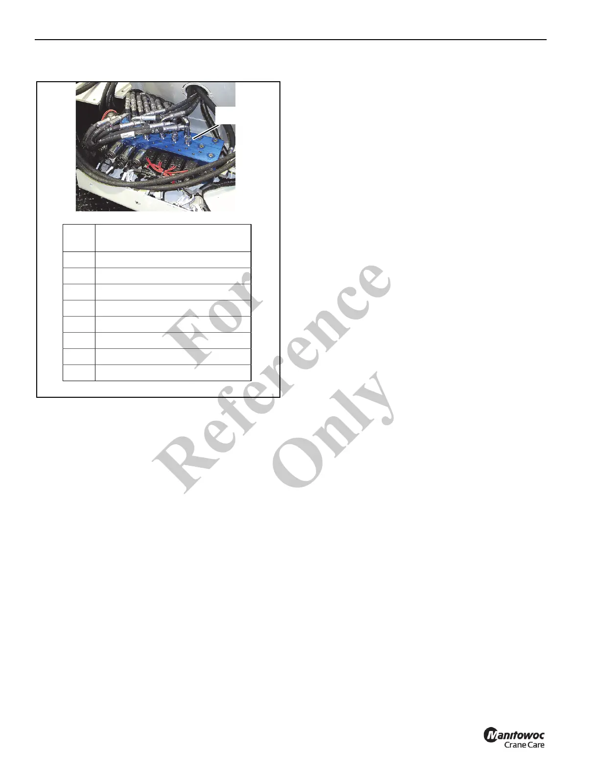
Hydraulic Remote
Control Valve
FIGURE 2-10
8143-8
Valve
Port
Remote Control Function
S1 Turn Right
S2 Boom Up
S3 Hoist down
S4 Telescope In
S5 Turn Left
S6 Boom Down
S7 Hoist Up
S8 Telescope Out
Fo
r
Reference
Only