OPERATING CONTROLS AND PROCEDURES 5540F/YB5515 OPERATOR’S MANUAL
3-10 Published 10-21-2011, Control # 055-03
Crane Level Indicator
See Figure 3-21 for the following procedure.
This is a bubble-type indicator that allows the operator to
level the crane when using the outrigger controls.
Boom Angle Indicator
See Figure 3-22 for the following procedure.
The boom angle indicator is a plumb arrow and a decal with
angular graduations from 0° to 69°. It is located on both sides
of the boom and is visible from the operator’s cab in most
boom positions. Use the indicator to determine the boom
angle when reading the capacity chart. (See Using the
Capacity Chart).
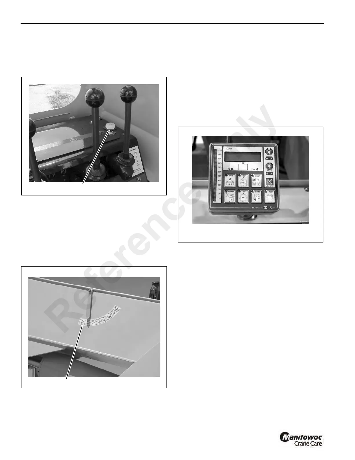
LSI Load Indicator Display Panel
The load indicator panel (Figure 3-23) displays load and
capacity related information and warns the operator when a
limit is exceeded. The operator is warned by a flashing light
on the display panel.
In conjunction with the display panel (receiver), there is a
transmitter and load pin attached to the boom head that
sends the load information to the display panel.
For operating instructions and battery changing instructions,
see the LSI “Universal Users Manual” supplied with the
crane.
See transmitter changeover instructions in Section 5 for
moving the transmitter to the down haul block when single
part line is used.
LSI Rated Capacity Limiter (RCL) - Optional
The rated capacity limiter is similar to the standard Load
Indicator, but instead of warning the operator when a load
limit is exceeded it stops the telescope out function and the
boom lower function and hoist up function when the load limit
has been exceeded. It uses a similar indicator panel as the
Load Indicator (Figure 3-23) and the same transmitter and
load pin, but the system also includes boom angle and boom
length sensors and transmitter that sends boom angle and
length information to the display panel. For operating
instructions, see the LSI Universal User Manual furnished
with the crane.
Optional Load Moment Indicator Display Panel
(Wylie)
See Figure 3-24 for the following procedure.
Provides visual indications of angle, load, radius, capacity,
etc. and allows the operator to set limits on these indications.
The display panel includes a digital display screen, LED
illuminated bar graph, eight indicator warning lights, audible
alarm and an operations key pad.
For operating instructions, see the LMI Operator’s Manual
furnished with the crane.
p1668
Crane Level Indicator, Typical
FIGURE 3-21
p1619
Boom Angle Indicator
FIGURE 3-22
p1386
Typical Load Indicator/Rated Load
Capacity Limiter Indicator Panel
FIGURE 3-23

 Loading...


