Grove Published 3-23-2020, Control # 654-04 4-75
GRT655/655L OPERATOR MANUAL OPERATING PROCEDURES
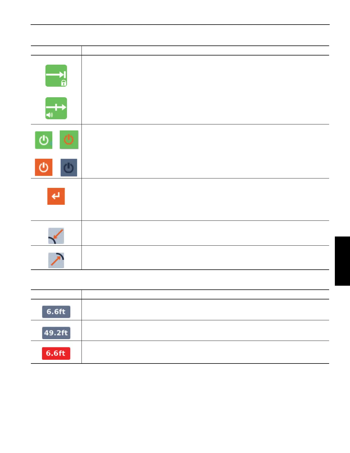
Table 4-8 Screen Symbols
In addition to the symbols that can be highlighted by the
arrow functions, the following are shown on the screen:
Symbol Description
Lock Out symbol and Alarm/Warning symbol - These symbols will not appear if the WRL is configured
for only the Lock Out Function or only the Alarm/Warning Function. Standard cranes are configured
for only the Alarm/Warning Function. Cranes configured for both functions, Lock Out and
Alarm/Warning, give the operator the ability to toggle between these two symbols, which indicate the
selection for the Lock Out Function (top symbol) or the Alarm/Warning Function (bottom symbol). The
selection for this configuration is toggled with an OK button (2, Figure 4-40).
Enable symbol (2X) - these symbols are used to enable or disable the inner and outer radius
limitation; which one is indicated by orange highlight of a symbol shown next to the inner or outer
radius circle with the crane graphic.
The selection for the enable/disable option is changed with an OK button. The symbols shown on the
top (green background) indicate that the limitation is enabled. The symbols shown on the bottom (not
green background) indicate that the limitation is disabled.
Accept Crane Position symbol (2X) - If the limitation is enabled, these symbols allow the acceptance
of the current crane position to be the limitation value (again which one is indicated by the position of
the symbol on the screen). If this symbol is highlighted (as shown here with orange background), and
the crane position is accepted with an OK button, then the value shown in the related Limitation Value
is updated to be the current crane position. If the limitation value is beyond allowable limits, a fault will
be generated, and a fault symbol will appear on the display.
This is the inner or minimum radius limitation indicator.
This is the outer or maximum radius limitation indicator.
Symbol Description
Inner Radius Limitation Value - this value is the currently specified hook radius limitation value for
Inner or minimum Radius.
Outer Radius Limitation Value - this value is the currently specified hook radius limitation value for
Outer or maximum Radius.
Current Crane Position - this value shown on the screen is the current crane position hook radius
value. It is the same value shown in the RCL screen. Note that in this example, the radius is at a limit,
and for that reason it would be shown highlighted in red.

 Loading...


