SET-UP AND INSTALLATION GRT8100 OPERATOR MANUAL
4-22 Published 3-25-2020, Control # 595-10
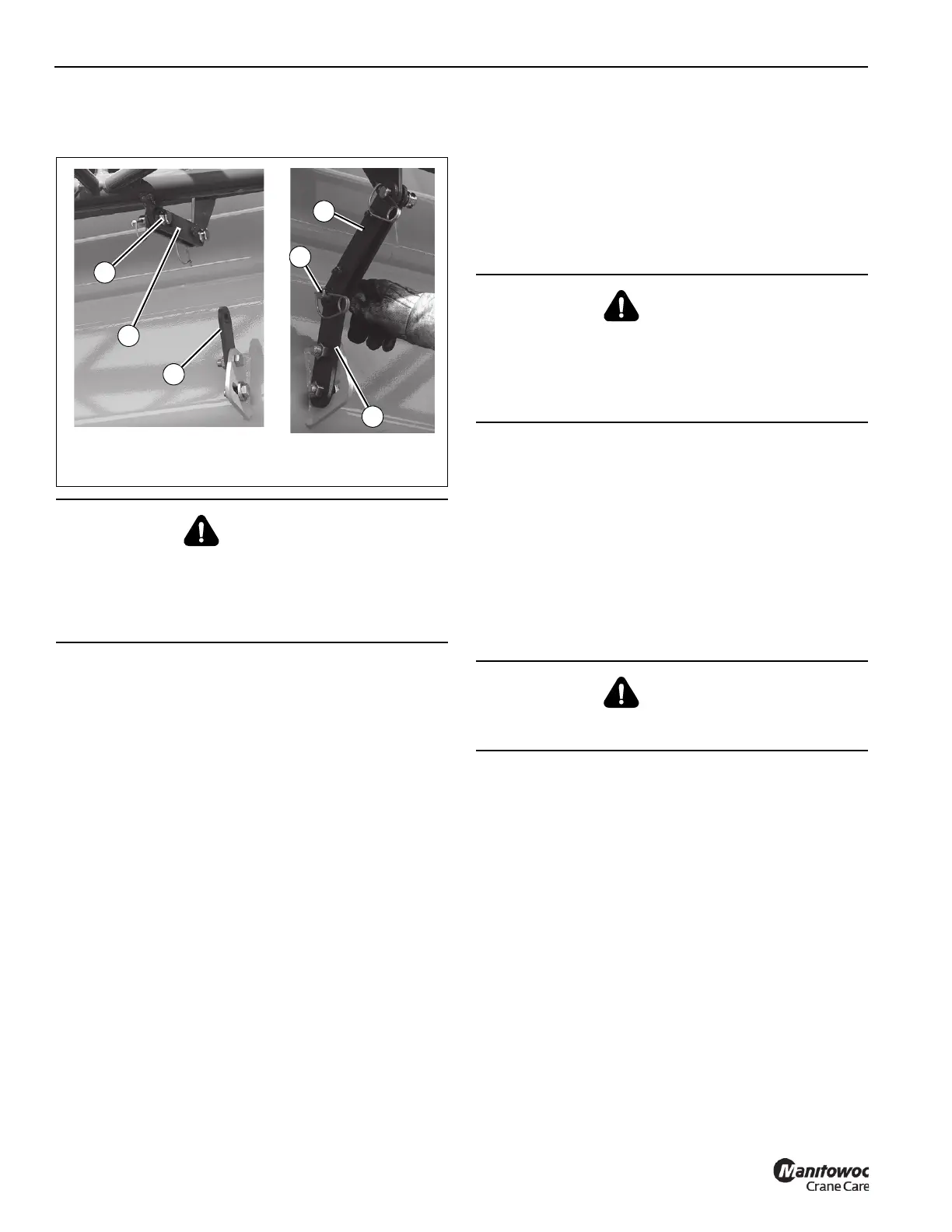
11. Move locking bar (9, Figure 4-20; 2, Figure 4-13) to
boom base attachment bar (1) and install pin (3). Secure
with retaining clip.
12. Remove attachment pin connecting the boom extension
fly section to the boom extension base section. Stow
attachment pin in the stowage holder on the boom
extension base section and secure with retaining clip.
Skip to step 14.
13. Remove attachment pin securing the boom extension fly
section to the rear stowage bracket assembly
(1, Figure 4-20) on the boom base. Stow attachment pin
in the stowage holder on the boom extension base
section and secure with retaining clip.
14. Using control pendant, extend middle stowage bracket
(10, Figure 4-20) until boom extension base section
anchor fittings align with boom nose attachment fittings.
15. Remove attachment pins from stowage lugs on right
side of boom extension base section and install into
upper and lower right anchor and attachment fittings of
the boom extension base section and boom nose.
Secure each attachment pin with a retaining clip.
16. Disconnect control pendant and replace caps.
17. Remove lock hitch pin (13, Figure 4-20) securing boom
extension base section to the front stowage bracket
(5, Figure 4-20) on the boom base. Stow lock hitch pin in
the stowage holder underneath the stowage bracket and
secure with retaining clip.
.
18. Raise boom slightly above horizontal.
19. Extend boom until boom extension base section is clear
of the middle stowage bracket ramp (10, Figure 4-20)
and the front stowage bracket pins (14, Figure 4-20) on
front stowage bracket assembly (5, Figure 4-20)
20. Slightly raise or lower boom to help control the boom
extension swing. Using rope attached to tip of the boom
extension base section, swing boom extension base
section in front of the boom nose until boom extension
base section anchor fittings engage with left side boom
nose attachment fittings.
21. Install attachment pin into the upper left anchor and
attachment fittings of the boom extension base section
and boom nose. Secure attachment pin with a retaining
clip.
22. Using the jack handle (4, Figure 4-14) stored on the left
side of the boom nose, extend boom extension
alignment jack (3, Figure 4-14) until the lower left anchor
and attachment fittings of the boom extension base
section and boom nose are aligned. Install attachment
pin and secure with retaining clip.
DANGER
Uncontrolled movement of the boom extension fly section
can cause death, injuries, or damage to equipment.
Ensure attachment pin securing the boom extension fly
section to the boom extension fly section rear stowage
bracket is in place.
FIGURE 4-13
6642-8
2
6642-9
1
3
2
3
1
DANGER
When erecting the boom extension base section, keep all
personnel and equipment clear of swing path.
Uncontrolled movement of the boom extension base
section can cause death, injuries, or damage to
equipment.
DANGER
Do not modify attachment anchors or fittings to allow
installation of the attachment pin.

 Loading...


