OPERATING CONTROLS AND PROCEDURES GRT880 OPERATOR MANUAL
3-72 Published 3-25-2020, Control # 643-04
• Extend and set outriggers and level crane.
• Raise, lower, and swing boom right and left at least 45
degrees.
• Telescope boom out and back in, ensuring all sections
extend and retract properly.
• Raise and lower cable a few times at various boom
lengths. Make sure there are no kinks and cable is
spooling on hoist properly.
NOTE: Carefully read and become familiar with all crane
operating instructions before operating the crane.
Using Your Load Chart
NOTE: One of the most important tools of every Grove
crane is the load chart in the crane operator's cab.
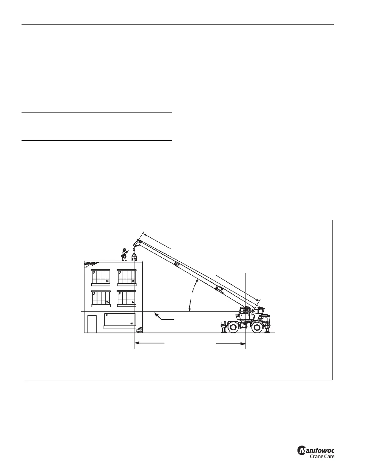
NOTE: Refer to Figure 3-29 for terms to know in
determining lifting capacities.
The load chart contains crane lifting capacities in all
allowable lifting configurations and must be thoroughly
understood by the operator.
The load chart is divided into capabilities limited by crane
structural strength and stability which is shown by a bold line
across the chart. Structural strength limits are above the line
and stability limits are below the line.
The left column is the load radius, which is the distance from
axis of crane rotation to load center of gravity. The top row
lists various boom lengths from fully retracted to fully
extended (with swingaway extension). The number at the
intersection of the left column and top row is the total load
limit for that load radius and boom length. The number in
parentheses below the total load limit is required boom angle
(in degrees) for that load. Use lower weight limit for the
two boom lengths.
Another important section is the range diagram. The range
diagram shows operating radius and tip height that can be
achieved at a given boom length and angle. If the operator
knows radius and tip height required for a specific lift, the
angle and boom length can quickly be determined from the
range diagram. Or, if an operator knows boom length and
angle, they can quickly determine tip height and operating
radius.
A lifting diagram is included for over-side, over-rear, and
over-front lifting areas. The lifting area diagram shows
locations of the outrigger jack cylinders in full extended
position are used to mark lifting area boundaries.
Another section contains notes for lifting capacities. Be sure
to read and understand all notes concerning lifting
capacities.
The load chart also gives weight reductions for Grove load
handling devices such as hookblocks, overhaul balls, boom
extension sections, etc., which must be considered as part of
CAUTION
Run engine at or near governed RPM during operation of
all crane functions.
FIGURE 3-29
OPERATING RADIUS
HORIZONTAL
BOOM ANGLE
M
A
I
N
B
O
O
M
L
E
N
G
T
H
AXIS OF ROTATION
4605
TERMS TO KNOW
 Loading...


