A_GC_SM_HDGASCOUNTERSERV_GT-UT-SERIES (Rev 1)Page 20
Griddle Adjustments
Griddle Spark Igniter
Garland has two different igniter systems on the griddle units:
1. Push-button piezo igniter system
2. Electronic Spark igniter system
1. Push-button Piezo igniter system (Figure 8) consists
of a small, spring-loaded hammer, which creates
voltage when a button is pressed. 120V electric
connection is NOT required; wires are needed to move
the electricity to an electrode close to the pilot. Proper
alignment is critical for better performance. Only one
spark is generated per press of the button. When
equipment installed above 8000 feet sea-level, lighters
with piezo-electric ignition are no longer reliable.
2. Electronic Spark Igniter System consists of an
Electronic Spark Generator (ESG) box (Figure 10),
a momentary switch (Figure 9), and electrical
components, plus wires to discharge a spark across a
gap between electrodes (spark gap). See below, section
2.3 ESG Technical Specification.
When electrical voltage connection is required, refer to
section Wiring Diagram.
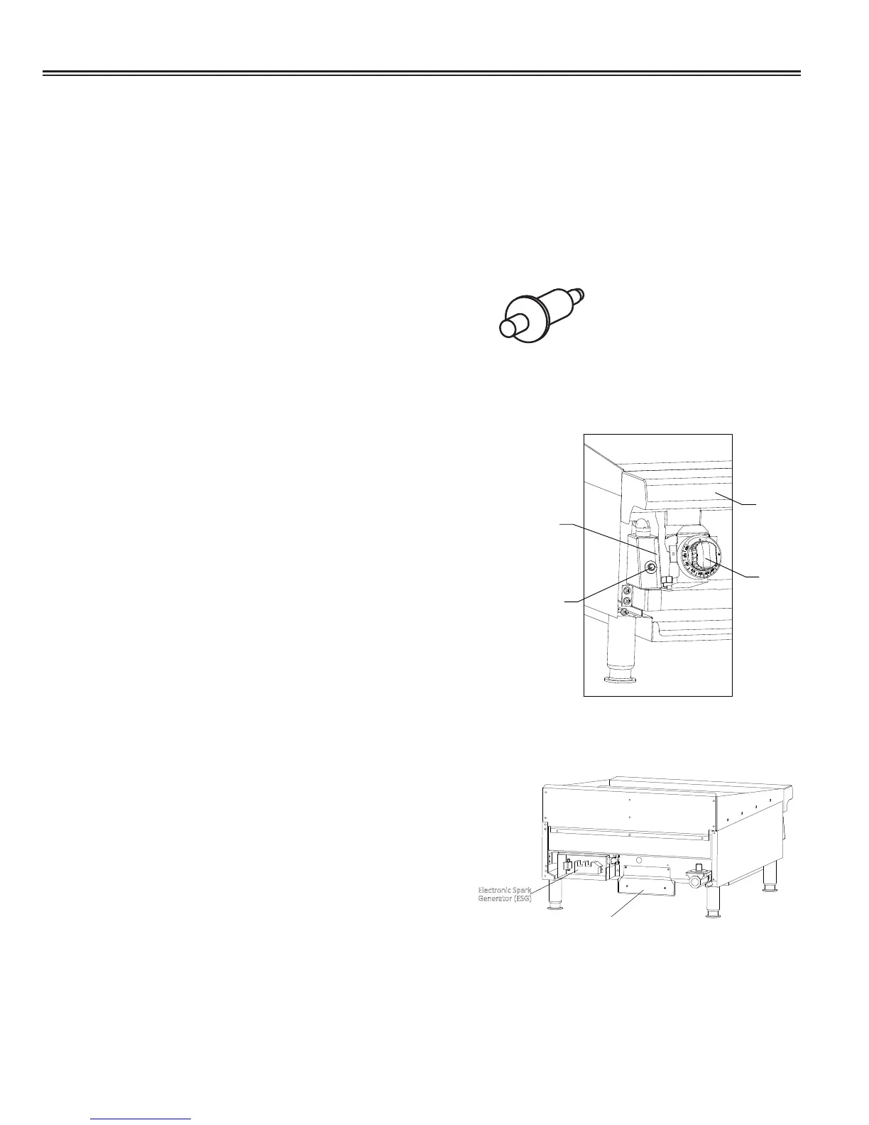
2.1 Remove, Test, and Replace a Momentary Switch
(MS)
a. Ensure power cord is unplugged.
b. Remove decorative dress nut off the
momentary switch
c. Remove knobs with set screws.
d. Remove the four (4) screws from front panel
and remove panel.
e. Griddle with SIT Thermostat: On the LEFT
hand side of the unit remove screw and the
momentary switch side panel (Figure 9).
Griddle with GS Thermostat: On the
RIGHT hand side of the unit remove screw
and the momentary switch side panel
(not shown).
f. Remove momentary switch nut and unplug
rear terminal wires.
g. Connect multi-tester probes on the
momentary switch terminals. Continuity
must be indicated when button is pressed,
if not, replace switch.
Figure 8
Momentary
Switch
Momentary
Switch Side Panel
Knob
Front
Rail
Figure 9. SIT Tstat and Momentary Switch
Electronic Spark
Generator (ESG)
ZĂƟŶŐ^ĞƌŝĂů
Plate
REAR VIEW
Figure 10

 Loading...