A_GC_SM_HDGASCOUNTERSERV_GT-UT-SERIES (Rev 1) Page 21
Griddle Adjustments (continued)
2.2 Removal and Replacement of Electronic Spark
Generator (ESG);
a. Verify the rating plate voltage to ESG specification.
See section 2.3 below.
b. Ensure power cord is unplugged.
c. Before removing ESG, check wires for continuity
in case a wire is damaged. Refer to section Wiring
diagrams.
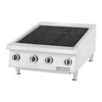
d. Remove the ESG front box panel located at the back
of the unit (Figure 10).
e. Unscrew the two screws at each side of the ESG
unit, and unplug the terminal wires. Remove the
ESG unit.
f. Replace ESG unit in reverse order.
Electronic Spark
Generator (ESG)
ZĂƟŶŐ^ĞƌŝĂů
Plate
REAR VIEW
Figure 10
2.3 ESG Technical Specification
Electronic Spark Generator (ESG)
Part # 4514749 Part # 4514750
Input Voltage (1-2) 220-240 +10%,-15% (1-2) 110-120 ±10%
Spark Type Repetitive, 3Hz at 230v Repetitive, 3Hz at 120v
Outlets (a-d) 4 (a-d) 4
Main Frequency 50-60 Hz 50-60 Hz
Power Consumption 0.8VA MAX. 0.6VA MAX.
Spark Gap 4 X 4 mm (0.157”) MAX. 4 X 4 mm (0.157”) MAX.
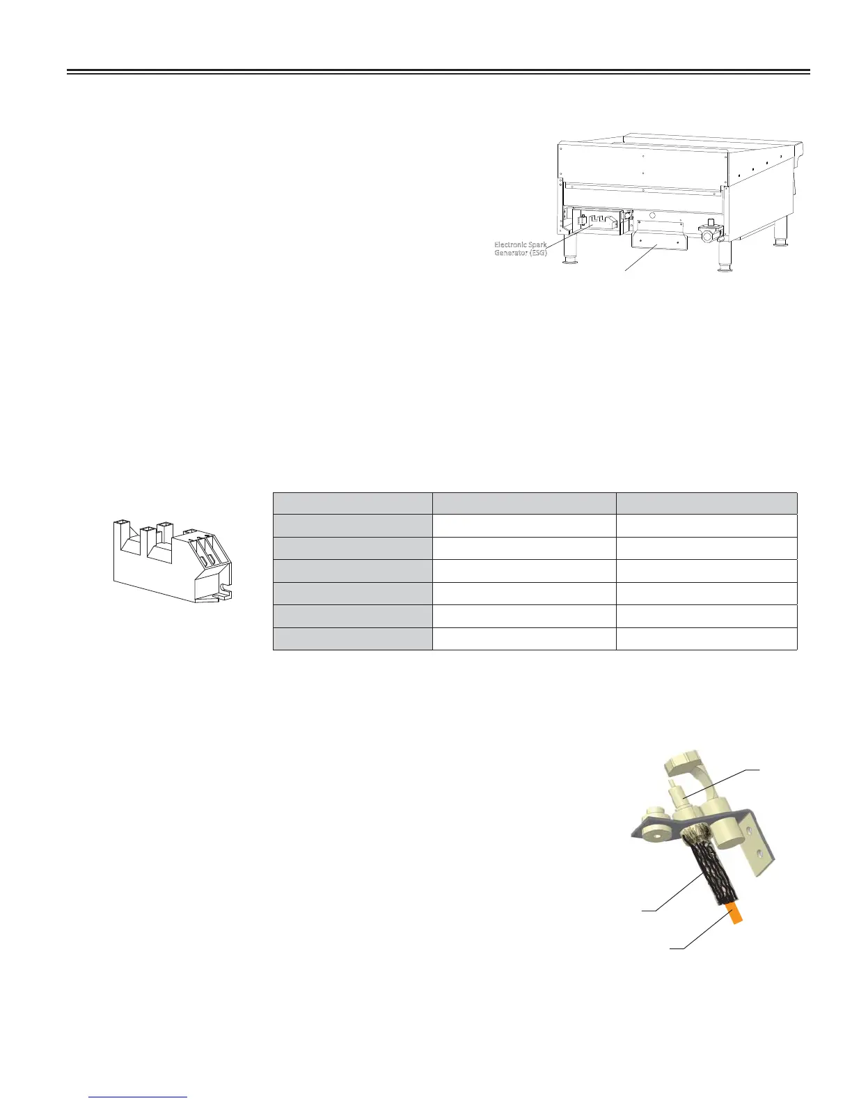
High Tension Lead (HTL) & Insulation
The pilot HTL is exposed to high temperatures where they are located.
IMPORTANT
Keep the insulation in place.
Insulation should cover wire, connector, plus bottom of electrode as
shown in Figure 11.
Wire Insulation
(black)
Wire (HTL)
(orange)
Electrode
Figure 11.
 Loading...