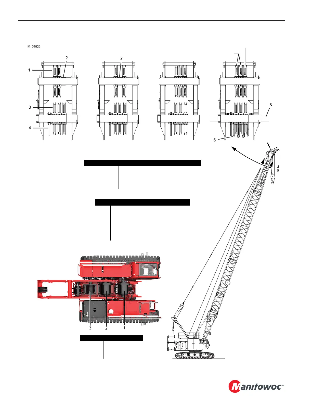
Item Description
1 Guide Sheave (Qty 2 or 3)
2 Spacer
3 Lower Boom Point Sheaves (Qty 3)
4 Dead-End Link (left side)
5 Duty-Cycle Rope Guard
6 Extended Shaft for Pile Driving Leads
ABCD
Configuration Description
A Two Load Lines
B Two Load Lines
C Three Load Lines
D Three Load Lines with Pile Driving Leads
Drum Description
1 Whip Hoist
2 Main Host
3 Auxiliary Hoist
CANNOT route wire rope from
this sheave to upper point.
CAN route wire rope from
these sheaves to upper point.
Figure 4-61