3-4 07-03-19 Control # 091-09
CONTROLS AND OPERATING PROCEDURES OPERATOR MANUAL 600H SERIES
• Outrigger beams extend or retract.
• Outrigger jacks are lowered or raised.
Independent Outrigger Component Operation
Position the outrigger toggle switch to other side or this side
and the control lever from neutral to the desired function. A
single outrigger component is activated.
• The selected outrigger beam extends or retracts.
• The selected outrigger jack is lowered or raised.
Side Midspan Outrigger Stop Pin
The side outrigger stop pin is located
on the side of the outrigger box and is
used to set the outrigger at the
midspan position. Rotate the side
stop pin 180° and extend the
outrigger beam until the pin drops
into the midspan hole and stops the
outrigger beam. Rotate the pin back
to the 0° position to retract the
outriggers.
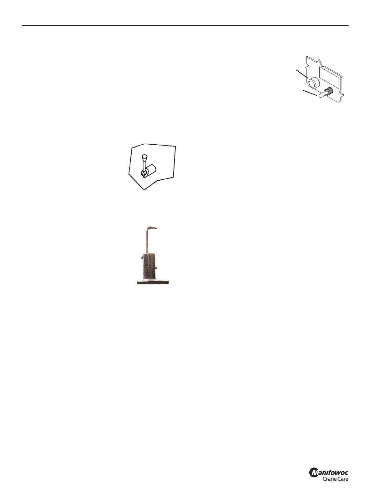
Top Midspan Outrigger Stop Pin
The top outrigger stop pin is located
on top of the outrigger and is used to
set the outrigger at the midspan
position. Rotate the pin to the lock
position and extend the outrigger until
the pin drops into the midspan hole
and the outrigger stops.
Foot Throttle
Depress the foot throttle to accelerate the truck engine
speed. Release to return to idle speed. Increasing truck
speed increases operating speed.
Emergency Stop Switch
Operate the switch to kill the truck engine under emergency
conditions. Switch must be reset to the “on” position to
operate truck from cab.
Horn
Operate horn button to warn fellow workers on construction
site of pending movement of crane.
RCL System
The RCL monitors crane operation and alerts the operator of
an impending tipping condition and disables the crane
functions.
RCL Power Switch
A toggle switch located in the
truck cab powers the RCL for
crane operation. An indicator
light comes on when the
system is activated.
NOTE: The RCL power
switch must be ON
before the crane cane
be operated.
Momentary RCL Override Switch
Rotate the key switch counterclockwise and push the RCL
override button on the operators console to enable crane
functions and remove the tipping condition.
NOTE: The key switch is located behind a door on the
drivers side of the operators console.
Load Chart
This chart is located on the side of the crane frame and
shows capacities of crane at various operating areas and
hoist capacities with appropriate reeving (See“Load Chart”
on page3-8).
Boom Angle Indicator
Located on either side of the base boom section and used to
determine main boom angle with respect to horizontal. For
reference only.
Boom length indicator
Located on either side of the second boom section. The
letters on the intermediate boom lengths correspond to the
letters on the load chart. The length indicators are used to
define boom length and with the load chart and load radius
are used to determine the maximum loads that may be safely
lifted. The load radius must be measured from the centerline
of rotation.
OPERATING PROCEDURES
You need to be familiar with the safety precautions outlined
in Section 2 before operating the crane.
Equipment Familiarization
All crew members should be familiar with the location and
operation of the controls, the correct operating procedure,
the maximum lifting capacities, and the Safety Precautions in
Section 2 of this manual. Carefully follow the operating
procedures outlined below and the information in the load
charts located in the crane cab.
Indicator
Light
RCL Power
Switch

 Loading...


