National Crane Published 8-01-2017 Control # 287-11 4-45
NBT40 SERVICE MANUAL BOOM MAINTENANCE
Use the following procedure to make adjustments to the jib
stowage bracket.
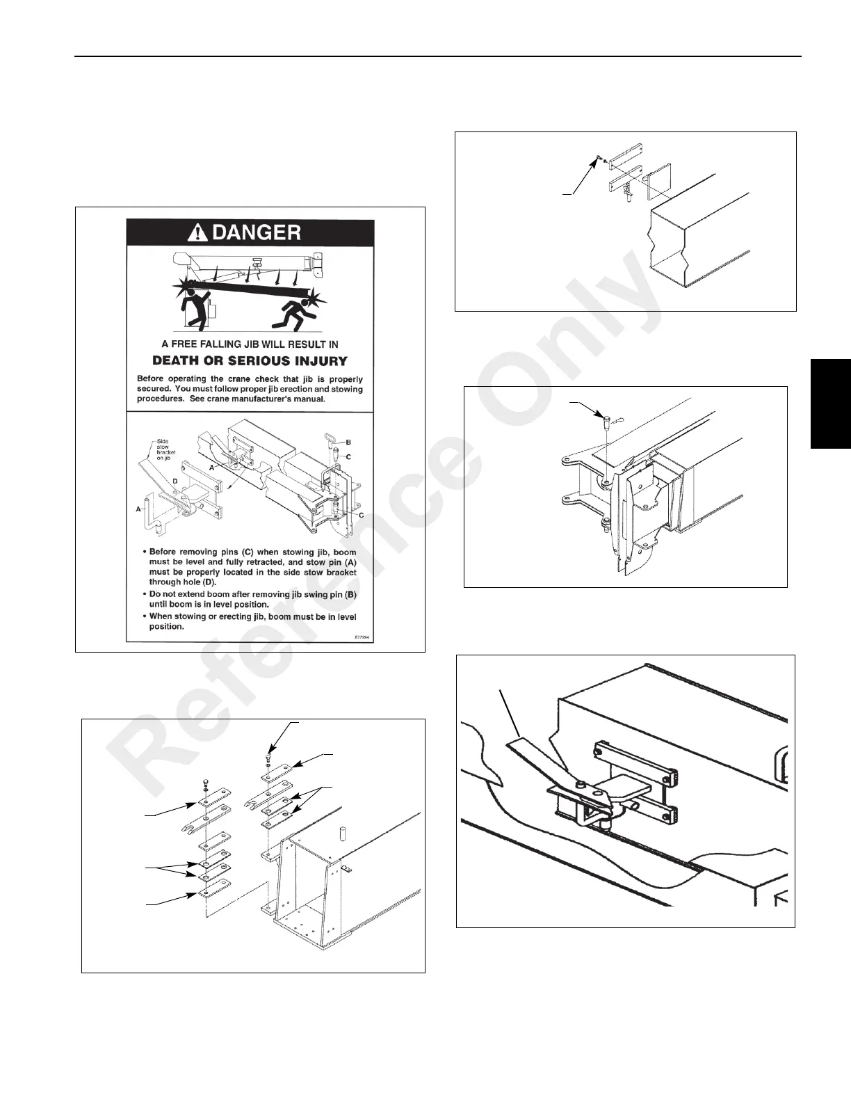
Before beginning this procedure read and understand the
following DANGER decal. Also review and understand the
Operator’s Manual Set-Up section 4 for jib safety, stowing
and deployment instructions.
1. Loosely bolt the two ear assemblies with shims and
bars as shown in Figure 4-24 to the side of the first boom
section.
2. Loosely bolt the hook assembly to the side of the first
boom section, Figure 4-25.
3. Extend the boom approximately one foot.
4. Using an overhead hoist, lift the jib assembly and align
and pin the jib to the boom sheave head, Figure 4-26.
5. With jib pinned to the sheave head, swing the jib parallel
to the boom and secure to the jib stowage bracket
Figure 4-27.
6. Slowly retract the boom until the jib ears are within
0.50 in of the ear assemblies on the first boom section.
Observe the vertical alignment of the jib ears and ear
assemblies and add or remove shims until the jib is
3/4 in GRADE 5
(TYP 4 PLCS)
0.38 BAR
0.06 SHIMS
0.38 BAR
0.06 SHIMS
0.38 BAR
FIGURE 4-24
FIGURE 4-27
STOWAGE BRACKET
7462-31
Reference Only
 Loading...


