MIC IN
INST IN
PHASE
INPUT
LEVEL
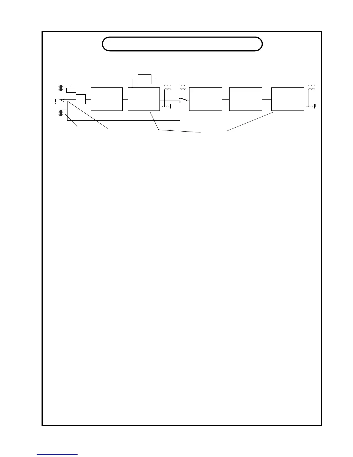
OVERVIEW and BLOCK DIAGRAM
COMPRESSOR
NEW PASSIVE
OPTO CIRCUIT
GAIN
SWITCH
MIC PRE
OUR 60dB TUBE
PREAMP
BALANCED
OUTPUT
LINE IN
UNBALANCED
OUTPUT
INSERT
INPUT
EQUALIZER
PASSIVE EQ
PULTEC STYLE
DE-ESSER
LIMITER
PASSIVE OPTO
LINE AMPLIFIER
TUBE CIRCUIT
BALANCED
OUTPUT
UNBALANCED
OUTPUT
TUBE
GAIN
STAGES
This block diagram is intended to give you a reasonable view of the signal ow in the VOX-
BOX. A few interesting aspects can be seen at a glance. First notice that when an instrument is
plugged it that it disconnects the LINE input. After the INPUT (level) control (which is a conduc-
tive plastic pot) the signal goes into the COMPRESSOR which is the rst major block in the chain.
Normally this is impossible because mic signals are so low that the noise introduced by a compressor
would be a problem even if the threshold control could see such a low signal. How do we do it ? We
use a light dependent resistor called an opto-isolator. This part is designed for audio applications and
is the same part we have been using in the Manley Electro-Optical Limiters. When light shines on this
special resistor some of the signal is shunted to ground which reduces the level. Adding this part to
the basic mic pre reduced the preamp gain by 0.1 dB and did not affect any other specication even
when compressing 15 dB. From the compressor the signal goes to the MIC PREAMP. Uniquely this
compressor up-stream can prevent mic signal clipping before the rst tube. The PREAMP is where
the mic signal gets boosted to line levels. This all-tube gain block is the same as the Manley Mono
Microphone Preamplier and quite similar in topology to the circuit in the Manley Pultec EQs and
Opto-Limiters. Notice how the GAIN is a feedback circuit, getting the signal from the output and
sending it back to the input. The signal is injected out-of-phase so that it acts to reduce gain, distortion
and noise. We chose a respectable range of operation for the feedback select. Not too little and not too
much which can cause problems with transient accuracy and imaging. You get to choose the optimum
amount for “your” sound. It is also not in the main signal path which we try to keep simple and pure.
At the end of this section is a transformer, that you can see, gets switched out to prevent any loading,
if you use the phone jack output. These outputs are intended to send to tape.
The rst thing in the EQ section is a switch to select the input. You can choose the LINE
INPUT (normally going to the rst stage Mic Preamp) or the output of the Preamp or a third input
called INSERT. INSERT is intended to be used so that this section is in the monitor path between
the tape output and the console. This way you can EQ and de-ess safely and not record them. Maybe
save it for the mix.. INSERT is also used to “insert” an outboard processor in the middle of things.
Another use for this input select switch is to compare the LINE in with the PRE OUT because there
is no “make-up gain” control (rather than just using the “Bypass”). This is a good, level consistent,
alternative. Yet another gain control here would have compromised the signal integrity and maximum
available gain on the mic preamp. Too bad.
The signal goes into the EQ and actually loses gain because the EQ is a simple passive circuit.
The signal later gets amplied by the next tube stage so that the full signal comes back to normal
levels. But rst..... it hits the DE-ESSER / LIMITER. Once again, this is a passive stage with far less
signal quality loss than outboard rack mounted devices. And once again we use our proven tube am-
plier circuit to restore levels and drive long cables.
TRANSFORMER
SYMBOL
SWITCHING
PHONE JACK
12
 Loading...