L
LINE
IN
E
PRE
OUT
M
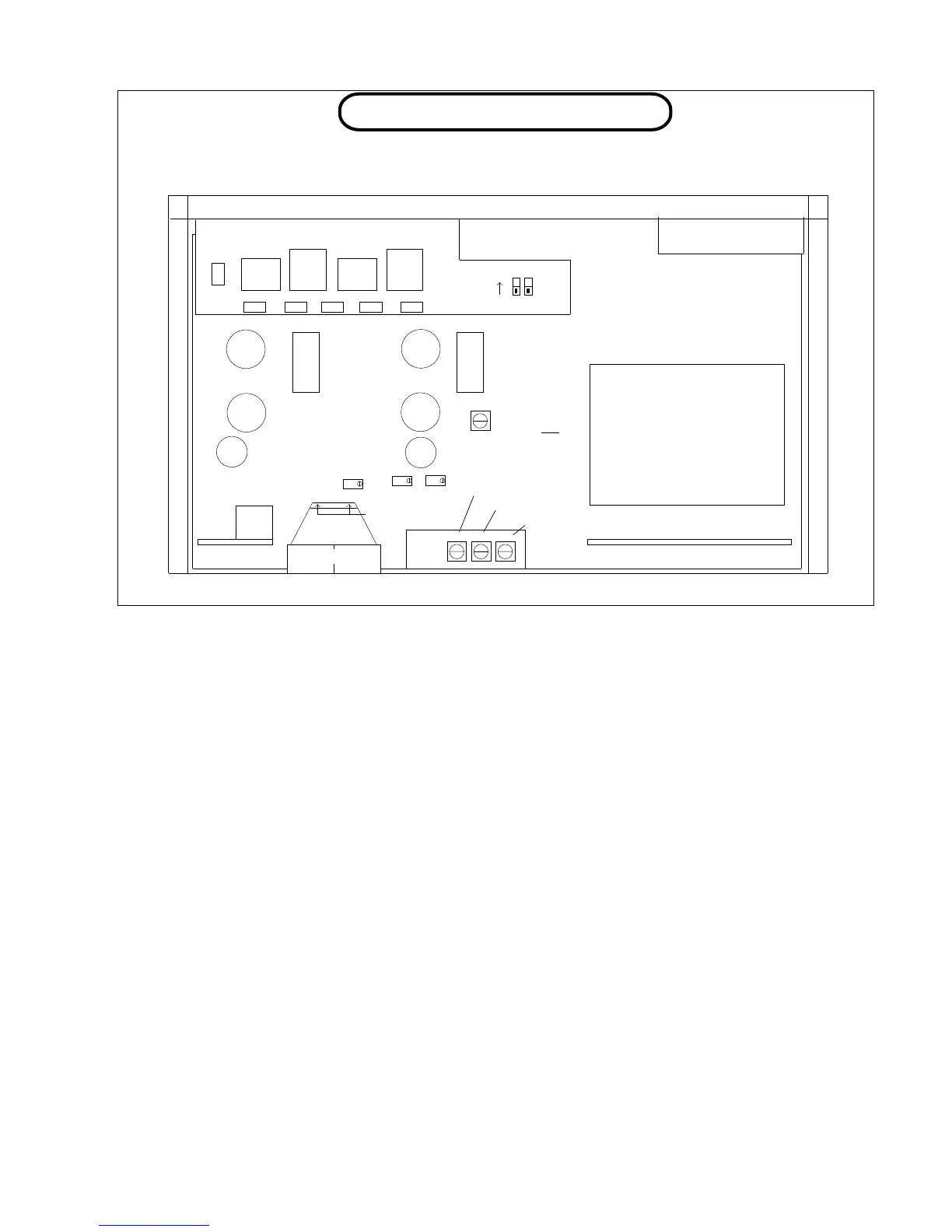
TUBE & TRIM LOCATIONS
INSERT
IN
E
E
EQ
OUT
M
EQ IN SELECT & MUTING
6414 6414
Low noise graded
12AX7 / ECC83
OPTOS
MIC
IN
MULTICAP OP
COUPLING
METER GR ZERO SET
3
METER DS GR CAL
12AX7 / ECC83
OPTOS
7 6
DS / LIM CAL
SUPER YELLOW LED LIGHTS
(remove 2 small phillips screws on
meter back to access)
D1 ON = No mute
D2 ON = Shorter mute time
D1,D2 OFF = Factory default
mute timer ON
ON
D1 D2
Power turn on delay
MULTICAP OP
COUPLING
1
EQ = UNITY GAIN
GND
METER COMP GR CAL
COMP AUDIO CAL
VU METER = +4.0 dB
12V FILAMENT
REGULATOR
5 4 2
POWER
TRANSFORMER
TUBES: We use 4 tubes in the VOXBOX. The substitutions listed just might work in a pinch but may
not give optimum performance. Get selected tubes from Manley Labs. A tube that does not
glow or has turned white inside needs to be replaced. A tube that makes too much audio noise
when tapped (microphonic) or is causing increased hiss should be replaced. The life of these
tubes averages more than 5 years but individual tubes cannot be predicted and may work 3
weeks or 30 years. Let the tubes cool before handling to prevent burns. The list is:
12AX7 MIC PRE GAIN STAGE; very low noise tube; a good quiet, ECC83 may
work but expect more noise & microphonics and uncalibrated gain.
12AX7 EQ GAIN STAGE; better 5751, ECC83 or 12AU7WA may work OK. 6414
LINE DRIVER; high current 12BH7A may work OK but are hard to nd
now, 12AT7A is the next best choice but does not have as much “poke”.
TRIMS: Each VOXBOX has been factory calibrated and tested at least four times. These trims should
not be re-adjusted unless absolutely needed and should only be done by a qualied techni-
cian. The function of each trim is labelled on the diagram above each trimmer and the order is
below. The complete procedure is on page 20. The technician will need these pages.
DIP SWITCHES: D1 if on, bypasses the turn-on delay. May be desired for live gigs or mobile record-
ing. D2 if on, shortens the turn on delay. If the unbalanced outputs are not used, then this
setting will be OK. There is only a small and “quick” thump that gets through the transformers
to XLRs.
19
EQ CAPS AND
INDUCTORS