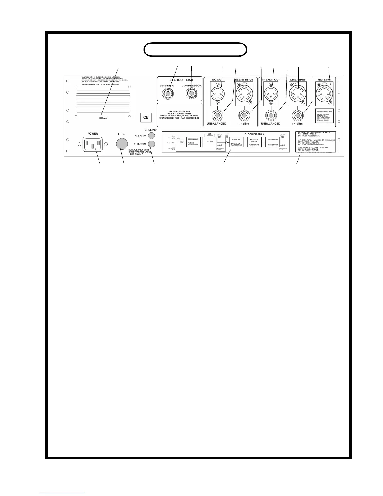
REAR PANEL
Q P O N M L K J I H G F
A B C D E
A. IEC POWER CONNECTOR: Use the IEC detachable power cable that was packed with the VOXBOX.
The correct mains voltage is factory wired for your country. The third pin ground is connected to the chassis
internally.
B. MAINS FUSE: Replace only with the same value and type which is 1 AMP SLO BLO. A generic type is
MDL 1 and its size is 1 1/4” X 1/4”. A second or third blown fuse may indicate an electronic problem needing
repair especially if it has turned black. If it appears to be a serious problem, you should send the VOXBOX to
your dealer or to MANLEY LABS for repair.
C. GROUND TERMINALS: These are used to nd or x hum or to prevent ground loops with a variety of
studio wiring techniques. The CIRCUIT GROUND may be also called audio ground or “technical earth” and it
simply is the common ground of the audio circuits in this unit. The CHASSIS GROUND is the third pin mains
ground and the chassis. Separating CHASSIS GROUND and CIRCUIT GROUND is the same as breaking
off the third pin of the AC plug except that it includes the chassis which is also probably grounded to the rack.
These two terminals are normally joined by a small piece of metal called a ground strap. If you loosen the posts
you can move the strap to the side - you can also lose the strap if you don’t re-tighten the posts. For some stu-
dio grounding techniques the AUDIO GROUND can be connected to the console with a piece of wire. If you
have a hum, experiment here rst.
D. BLOCK DIAGRAM: Shows a simplied drawing that shows the basic signal ow. This diagram is also on
page 12 in this manual.
E. CONNECTOR PIN-OUT: A list of how the XLR and phone jacks are wired that might help the person
building the cables. This info is also in detail below.
F. MIC INPUT: The mic cable gets plugged in here. 48 volt Phantom Power is available on this connector (see
page 6). The input impedance is 2400 ohms and is matched for most professional mics. The PIN-OUT of all
the XLRs is as follows:
PIN 1 = CIRCUIT GROUND = SHIELD
PIN 2 = HOT = positive going signal +
PIN 3 = LOW = negative going signal -
G. LINE INPUT. For balanced or unbalanced +4 line level sources. Transformer coupled 1/4 inch phone jack.
The PIN-OUT is :
BALANCED - (using a stereo phone plug ) UNBALANCED - (using a mono or stereo plug)
TIP = HOT = positive + TIP = SIGNAL = HOT
RING = LOW = negative - (RING = GROUND = SHIELD)
SLEEVE = GROUND = SHIELD SLEEVE = GROUND = SHIELD
9