EasyManua.ls Logo

MantelMount MM700 User Manual

MantelMount MM700
20 pages
To Next Page IconTo Next Page
Page #1 background imageLoading...
Page #1 background image
MM700 Installation Instructions
Please read this entire manual before you begin.
Do not unpack any contents until you verify all requirements on PAGE 4.
If you have any questions, visit our website or call (800)-897-9755.
Do not let children operate, pull on, or hang from
MantelMount. Do not let children push
MantelMount upward to the top position - this will
cause the mount to slam against the wall due to
the upward force of the springs. Only a person
tall enough to control the mount all the way to
the top should operate MantelMount.
This product contains small parts that can be
a choking hazard. Do not let children play
with any of these small parts! Keep children
away from the work area during installation.
!
CAUTION:
Do not use this product in any way, or for any
purpose, that is not specifically described in these
instructions. MantelMount is not responsible for
damage or injury caused by incorrect installation
or improper use.
!
CAUTION:
MantelMount has four different adjustments
that must be made after the installation is
complete in order to operate properly.
IMPORTANT:
This product is intended to be installed by
professional installation contractors, or persons
familiar with the tools and methods required for
this installation. If you are not sure about your
ability to perform this installation, you must
contact a professional. MantelMount is not
responsible for damage or injury caused by
incorrect installation or improper use.
!
CAUTION:
!
WARNING!
IMPORTANT SAFETY INSTRUCTIONS - SAVE THESE INSTRUCTIONS
MantelMount MM700 PAGE 1
www.MantelMount.com
The bottom travel stop is adjusted with two
screws so that the TV and mount do not
lower all the way into the mantel.
A slight amount of tilt in the UP position can
be added or removed by using one screw
inside the lifting mechanism.
The side-to-side swivel stops are adjusted
with two screws so that the TV does not
swivel into the mantel.
The main bolt adjusts the lifting force to
accommodate different TV weights. All TVs
within the weight range should stay in the UP
and DOWN positions when adjusted properly
Question and Answer IconNeed help?

Do you have a question about the MantelMount MM700 and is the answer not in the manual?

MantelMount MM700 Specifications

General IconGeneral
ModelMM700
BrandMantelMount
ConstructionSteel
Mounting TypeWall Mount
Installation Hardware IncludedYes
Cable ManagementYes
TypeFull Motion
VESA Compatibility200x200 to 600x400
FinishPowder Coated
Wall Plate TypeSingle

Summary

General Safety and Important Information

Choking Hazard and Child Safety

Product contains small parts; keep children away from work area and mount.

Professional Installation Guidance

Intended for professionals; contact if unsure. MantelMount not liable for incorrect installation.

Product Usage and Warnings

Use only as described. Do not let children operate. Avoid slamming.

Key Post-Installation Adjustments

Four adjustments required for proper operation: main bolt, travel stop, tilt, and swivel.

Tools and Component Verification

Required and Optional Tools

Lists necessary tools and optional tools for installation.

Component Check Before Installation

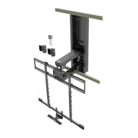
Verify all parts are included and undamaged before proceeding.

Optional Side Swivel Kit Installation

Components of the Swivel Kit

Lists the parts included for the optional side swivel kit.

Critical Installation Requirements

Fireplace and Mantle Compatibility

Decorative fireplaces only, max 110°F, mantle extension limits.

Wall Structure and Thickness

Requires wood stud frame only, wall covering max 5/8 inch thick.

Television Specifications

Weight 25-115 lbs, screen size >44 inches, VESA compliant.

Required Vertical Space

Space above mantle must accommodate TV height and mantle extension.

Attaching Brackets to Television

Determine TV Back Type

Use Vertical Brace to identify flat or irregular TV back for spacer needs.

Select Appropriate Mounting Screws

Choose correct screw diameter and length for secure thread engagement.

Understanding Brace to Wall Plate Offset

Vertical Braces are 1 inch higher than Wall Plate for height calculation.

Mounting Brackets and Initial Measurements

Brace Extender Mounting Options

Mount Brace Extenders above TV (no soundbar) or below (with soundbar).

Attaching Horizontal Brace and Handle

Connect Horizontal Brace and Center Handle to Vertical Braces.

Measure for Wall Plate Placement

Measure distance from Vertical Braces bottom to TV bottom for next step.

Wall Plate Positioning and Stud Identification

Calculate Vertical Wall Plate Position

Determine required height based on mantle extension and previous measurement.

Locate Mantle Centerline

Measure and mark the center of the mantle on the wall.

Locate and Mark Wall Studs

Use a stud finder to find studs and mark their centers for secure mounting.

Wall Plate and Lifting Mechanism Installation

Position and Mark Wall Plate Holes

Align, center, level, and mark the Wall Plate directly on stud centers.

Pre-drill Mounting Holes

Drill 4 holes to 2.5 inches depth, considering wall covering thickness.

Secure Wall Plate to Studs

Attach Wall Plate with Lag Bolts and Washers into stud centers. Avoid overtightening.

Install Lifting Mechanism

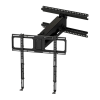
Insert Lifting Mechanism into Wall Plate slots and secure with screws.

Swivel Adjustments and Optional Kit

Standard Swivel Range

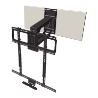
MantelMount offers 35° swivel left and right.

Side Swivel Kit Installation

Instructions for removing and re-installing the Swivel TV Plate with the Side Swivel Kit.

Optional Signal Cable Routing

Using Routing Boxes and Conduit

Install routing boxes with metal conduit to route signal cables through framed areas.

Cable Type and Noise Warning

Routing boxes are for signal cables only. Keep power cables separate to avoid noise.

Local Code Compliance for Conduit

Verify local building codes for minimum conduit distance from fireplace components.

Installing Optional Cable Routing Boxes

Mark and Cut Wall Openings

Trace routing box locations and cut openings in wall covering for studs.

Secure Box and Conduit

Attach conduit to box, secure box to studs, and ensure proper fit.

Feed Signal Cables Through Conduit

Push signal cables through the installed conduit from the upper to lower opening.

Cable Management System

Install Cable Tie Anchors

Insert cable tie anchors into the lower arm of the lifting mechanism.

Secure Cables with Ties

Use cable ties to attach cables sideways to the lower arm, allowing for movement.

Hanging Television and Setting Lift Force

Attach TV Brace to Lifting Mechanism

Install the TV Brace to the Lifting Mechanism and secure with screws.

Two-Person TV Hanging Procedure

Requires two people to safely hang TV and insert Safety Bolt.

Pre-set Lifting Force Adjustment

Adjust main bolt to set gas spring force based on TV weight for smooth operation.

Securing the Television

Hang TV and Check Clearance

Hang TV onto braces, check for mantle clearance, and be prepared to adjust.

Center and Level TV

Center TV on frame, adjust sideways up to 2 inches for balance and level.

Secure TV Brace

Install screws through the TV Brace into the Vertical Braces to lock the TV in place.

Fine-Tuning Adjustments

Adjust Bottom Stop Position

Loosen locknuts and adjust bottom stop screws for desired downward travel.

Adjust Side Swivel Stops

Loosen locknuts and adjust swivel stop screws for desired left/right limits.

Fine-tune Lifting Force

Adjust main bolt to ensure TV gently stays in lowered position.

Vertical Tilt and Wall Cover Finishing

Adjust Vertical Tilt

Use large screw to add or remove vertical tilt. Do not overtighten screw.

Prepare Wall Cover for Cables

If cable box installed, measure and cut an access hole in Wall Cover.

Paint Wall Covers

Optionally paint the Wall Covers to match the surrounding wall.

Final Assembly and Safety Bolt Removal

Attach Wall Covers

Install Wall Covers using adhesive Velcro strips to conceal the mount frame.

Remove and Store Safety Bolt

Remove Safety Bolt and Nut once TV is secured. Store safely for future use.

Operational Cautions

Never release handle fully upright. Control lifting process. Keep children away from mount.

Related product manuals