5
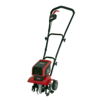
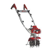
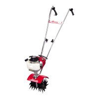
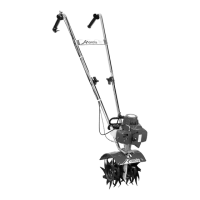
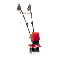
Your MANTIS Tiller comes partially assembled. You must
install only the handlebars, the carrying handle, and the tines.
This will take just a few minutes if you follow the directions.
First, take all items out of the carton. But do not remove
the cardboard from around the Tiller’s base.
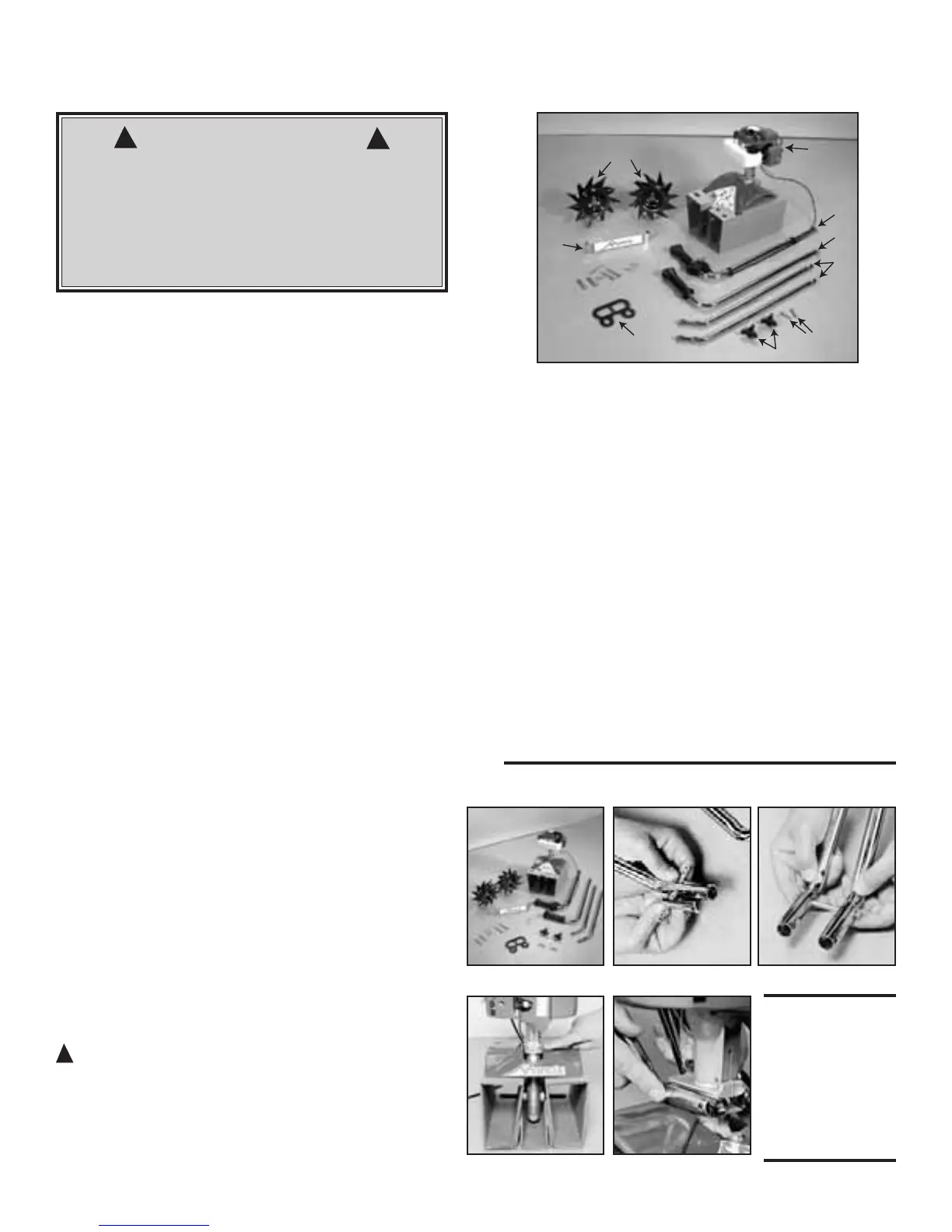
The list at the right, shows the parts that come with your
tiller. Check to make sure you have them.
The bag of hardware is in the plastic bag containing the
Owner’s Manual and Video.
To assemble your MANTIS Tiller, you’ll need two 7/16”
wrenches or two adjustable wrenches. We suggest that you
install all nuts and bolts only “finger tight”
— that is, one-
half to one full turn — until you’ve completed assembly.
The nuts are self locking, but you must use a wrench to
tighten them completely.
ASSEMBLY
WARNING • DANGER
IMPROPER ASSEMBLY OF THIS TILLER CAN RESULT IN SERIOUS
INJURY. MAKE SURE TO FOLLOW ALL INSTRUCTIONS
CAREFULLY.
IF YOU HAVE ANY QUESTIONS, CONTACT YOUR LOCAL
AUTHORIZED MANTIS DEALER
!
!
Quantity Description *Key #
1 Upper Handle Assembly 2
1 Upper Handle Throttle Side Assembly 1
2 Lower Handles 3
1 Pair Tiller/Cultivator Tines 26/27
1 Engine Assembly (includes Fender
Guard & Worm Gear Transmission) 8, 7, 42
1 Handle Brace 5
1 Plastic Carrying Handle 29
1 Bag of Hardware Containing:
2 Cap Screws 34*
4 Lock Nuts 35
2 Bolts (3” long) 36
2 Tine Retaining Pins 28
2 Handle Clamps 38
1 Throttle Clips 6
2 Bolts 39
2 Knobs 40
*These numbers are the same numbers shown on the Parts Layout on
page 16.
HOW TO ASSEMBLE LOWER HANDLES
To identify part numbers, see pages 6 and 27.
1. Use the protective cardboard sleeve to stabilize
your tiller. Stand the engine assembly (#8) up.
2. Lay the handle parts within easy reach. You’ll need
one of the handle clamps (#38) and one of the lower
handles (#3). Note that the lower handles have a short leg
on one end. (Picture 1)
3. Fit the handle clamp along the outside of the short
leg. Line up the holes on the clamp and the leg.
4. Choose one of the two 3-inch bolts (#36). Slide it
through the first set of holes — near the elbow where the
lower handle curves. (Picture 2)
5. Now slide the other lower handle onto the 3-inch
bolt. (Picture 3.) Fit the other clamp onto this other
handle’s short leg. Add a nut and tighten finger tight.
6. Locate the worm gear housing. It starts just above —
and extends down through — the tiller’s red fender guard.
You’ll notice that there’s a recessed channel on either side
of the housing’s top. (Picture 4.)
7. Take the lower handles that you’ve just put together.
Slide them into the two recessed channels.
Make sure you insert them from the rear of the tiller
(gasoline tank faces the operator)... so that the bolt fits
along the back of the housing. (Picture 5)
8. Slide the second 3-inch bolt through the second set of
holes in the short legs. Add a nut and tighten finger tight.
!
Picture 1 Picture 2 Picture 3
Picture 4 Picture 5
NOTE: THE
LOCK NUTS
ARE STAMPED.
FINGER TIGHT IS
APPROXIMATELY
1/2 TO 1-1/2
TURNS.