I
EB
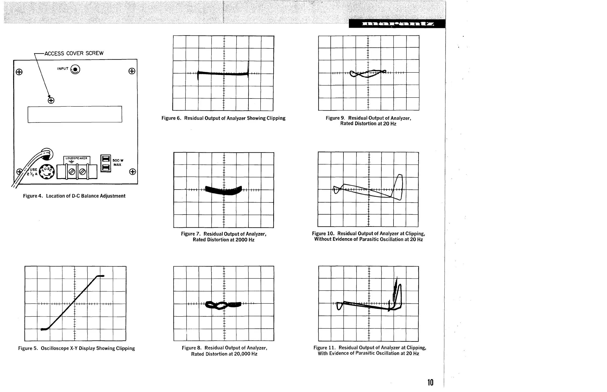
ACCESS
COVER
SCREW
INPUT@
SE©\lS~
'I
A
'-"
2
~
~!500W
~
MAX
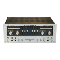
Figure 4. Location of
D-C
Balance Adjustment
,,.
-
~
/
~/
~v
~v
-
ffi
ffi
Figure 5. Oscilloscope
X-Y
Display Showing Clipping
Figure 6. Residual Output of Analyzer Showing Clipping
Figure 7. Residual Output of Analyzer,
Rated Distortion at
2000
Hz
-
C
-
•
~
I
Figure 8. Residual Output of Analyzer,
Rated
Distortion at 20,000
Hz
-
--
'-,;
:,oll;;
.~
--
.....
Figure
9.
Residual Output of Analyzer,
Rated Distortion at
20
Hz
,...
r--
I
.~
r--..
V
----
r--
,___-.......:..
.........
j
,-....,
Figure 10. Residual Output of Analyzer at Clipping,
Without Evidence of Parasitic Oscillation at 20
Hz
I
'
-
4
V
;
_..
..
Figure 11. Residual Output of Analyzer at Clipping,
With Evidence of Parasitic Oscillation at 20
Hz
10