INTRODUCTION
This service manual
was
prepared
for
use
by
Authorized Warranty Stations and contains service
data
for
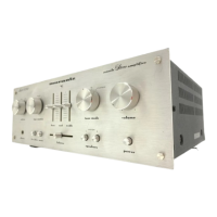
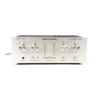
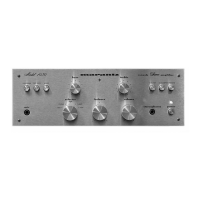
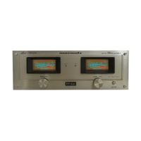
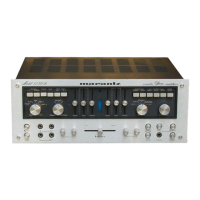
the Marantz Models 14 and 15 Solid State
Amplifiers.
Adjustment information and troubleshooting hints
included in this manual are intended for use by the
knowledgeable and experienced technician only. All
instructions should
be
read carefully and understood
fully before proceeding with any service.
No
attempt
should
be
made to proceed without a good under-
standing
of
the Solid State Amplifier operation and
an
adequate proficiency
in
the
use
of
the test equip-
ment required
for
servicing.
Symptoms (and their remedies) listed
in
the
Troubleshooting Section are those which might occur
in some
units-based
upon information derived from
a significant sampling of units
in
the field.
As
the
Marantz Company becomes aware of other field prob-
lems, supplementary service bulletins will
be
issued
to all stations. To improve this service, all problems
(and their solutions) not covered
in
this service
manual should
be
brought to the attention of the
Service Manager at our
New
York location.
NOTE
Performance Verification, Output Trim-
ming, and Trouble Analysis Procedures in
this manual apply to a Model
14
amplifier
or
to
each
of
two modules comprising a
Model 15 amplifier.
CIRCUIT
DESCRIPTION
The signal to
be
amplified is fed from the input
jack through
CS
and R14 to the base of Q103.
Refer to the schematic diagram of the amplifier,
Fig-
ure 13. Resistor R14 and capacitor
C9
is
an
R-F
filter
which bypasses to ground any
R-F
appearing at
the input jack. This eliminates the possibility of
detected
R-F
from reaching the loudspeaker termi-
nals and causing unwanted signals in the loudspeak-
ers. Q103 is one-half
of
a differential amplifier
consisting of Q102 and Q103.
The
constant current
supply for this differential amplifier is
QlOl.
Ql0l
is
biased by a network
of
resistors, diodes, and a
zener diode in order to establish a slow turn-on
characteristic, and a constant current
of
about 4
milli-amperes. Slow turn-on allows all other equip-
ment to
be
stabilized before sound
can
be
heard
from the loudspeakers.
The combination
of
Cl,
Rl,
R2,
and R17 comprise
a time constant circuit for turning
on
Ql0l.
If
QlOl
is not turned on, Q102 through Q106 will not
be
turned
on
either, because the drive current for these
transistors
is
derived from
QlOl.
As
a result, there
will not
be
any current drive
in
the printed circuit
board. Without current drive there will
be
no
current
flowing through Q107 and the bias network. Q108
and
Ql
11
will remain at cut-off, and therefore the
output voltage will
be
at virtual ground or zero.
During turn-on, the voltage present at the junction
of
Cl
and CR104 may
be
negative. To prevent this
from affecting the turn-on time constant, CR104
clamps this point to ground during turn-on. CR104
also provides a discharge path to ground for
Cl
dur-
ing turn-off. Rapid discharge of
Cl
ensures proper
functioning
of
the slow turn-on feature in the event
the amplifier is turned-on immediately after
it
has
been
turned-off. The network consisting of
CRlOl,
CR102, CR103, and
R4
insures
that
QlOl
always
delivers a constant current of 4 milli-amperes under
high or low line voltage conditions.
The differential amplifier consisting
of
Q102 and
Q103 delivers current to a second differential
am-
plifier Q105 and Q106.
In
order to supply a push-
pull drive to drivers Q108 and
Ql
11, current inver-
sion
is
required. This
is
accomplished in Q104, a
PNP
transistor functioning
as
a current inverter.
Q105 delivers current to the
base
of
Q104, which
inverts the signal. The collector
of
Q104
and
the
collector of Q106 supply the plus and minus drives,
1