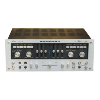
DISASSEMBLY
INSTRUCTIONS
MODEL
14.
To disassemble the Model 14 Solid State
Amplifier
for
servicing, proceed
as
follows:
1. Remove the four larger Phillips
head
screws
from the top grill and remove the grill.
2. Remove the rubber feet securing the grill at
the bottom of the amplifier. Remove the grill.
3. Remove the four Phillips
head
screws that
se-
cure the rear panel to the main chassis. This will
permit access to the printed circuit board.
4. The other components are accessible by remov-
ing
four
Phillips head screws holding the U-shaped
extrusion
on
which the rear panel
is
mounted.
Two
of
these screws are located at
each
side
of
the amplifier.
MODEL 15.
To
disassemble the Model 15 Solid State
Amplifier
for
servicing, proceed
as
follows:
1. Disconnect the power cord inter-connecting the
two modules.
2. Being very careful not to mar the panel finish
or the
hex
head
bolts, remove the four bolts that
secure the panel to the amplifier modules.
3. Gently pull the panel forward and disconnect
the pilot lamps.
4. Loosen and remove the
No.
8 cap screws using
a
9/64-inch
Allen wrench.
5.
Remove the four Phillips
head
screws from the
center plate that holds the two modules together.
The
plate is at the rear
of
the amplifier.
6.
Separate the modules and proceed with dis-
assembly of the Model 14.
PERFORMANCE
VERIFICATION
TEST
PROCEDURE
A.
TEST EQUIPMENT. Refer to Table I for the test
equipment required.
B.
PRELIMINARY PROCEDURE.
1. Set up the amplifier module to
be
tested and
the test equipment
as
shown in figure 3.
2.
If
a Model 15
is
to
be
tested, disconnect the
interconnecting power cord between modules
and test one module at a time.
3. Make sure that the connections between the
the resistive load and the
LOUDSPEAKER
ter-
minals
of
the amplifier module have negli-
gible resistance compared with the resistance
of
the load itself. Appreciable resistance
in
the wiring adds to the total load, resulting
in
inaccurate measurement
of
output power.
C.
IDLING CURRENT AND
D-C
BALANCE
TEST.
1. Connect a shorting plug to the INPUT jack
of
the amplifier module.
2. Make sure that the Variac is set
tor
zero volt
before applying line power to the amplifier.
3. Turn up the Variac slowly while observing the
voltmeter and the wattmeter.
When
the line
voltage reaches approximately
90
volts, the
amplifier should turn on, and the line watt-
meter should indicate between 5 and 15
watts. If the wattmeter indicates either zero
watt or greater than
100
watts, a defect
exists. Turn off the Varaic
and
refer to the
Trouble Analysis section
of
this manual.
4. Advance the Variac until the voltmeter indi-
cates 120 volts. If the wattmeter does not
indicate
30
± 1 watt, adjust bias potenti-
ometer R30,
as
follows:
a.
Remove the top grill cover from unit.
b.
Using a long, narrow, insulated screw-
driver, adjust bias control R30 until
30
watts
is
obtained
on
the wattmeter. The
bias control
is
located
in
the lower left
hand corner
of
each
module.
5.
Turn
ott'the
Variac (using switch only) and
discharge C15 and
C21
(the large electro-
lytics), using a 10-ohm, 1-watt resistor.
Do
not
use
a screwdriver to discharge the
capacitors.
6.
Set the controls
of
the
DC
VTVM
for
plus (
+)
DC
measurement
on
the 1.5-volt scale. Short
the
VTVM
test leads together and offset the
pointer to the zero center
of
the scale.
7. Connect the negative lead
of
the
VTVM
to the
ground (gray)
LOUDSPEAKER
terminal
a_nd
the positive lead to the hot (red) terminal
on
the amplifier.
5
'.