2.7
3.3
3.9
~OFF
D
4.7
BLK
5.6
6.8
8.2
10
2.7
3.3
3.9
~OFF
D
4.7
BLK
5.6
6.8
8.2
10
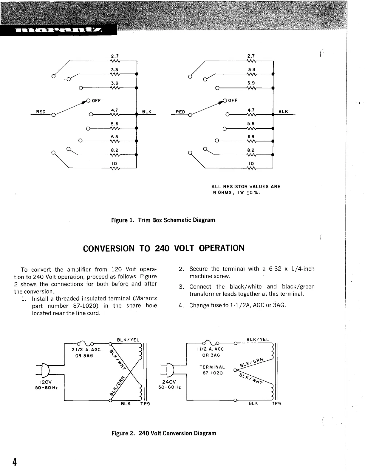
ALL
RESISTOR
VALUES
ARE
IN
OHMS,
IW
:!:.5•/o.
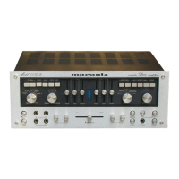
Figure
1.
Trim
Box
Schematic
Diagram
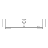
CONVERSION
TO
240
VOLT
OPERATION
To convert the amplifier from 120 Volt opera-
tion to 240 Volt operation, proceed
as
follows. Figure
2 shows the connections for both before and after
the conversion.
1.
Install a threaded insulated terminal (Marantz
part number 87-1020)
in
the spare hole
located near the line cord.
120v
50-60
Hz
2. Secure the terminal with a 6-32 x
1/4-inch
machine screw.
3. Connect the
black/white
and black/green
transformer leads together at this terminal.
4. Change fuse to
1-1/2A,
AGC
or
3AG.
240V
50-60Hz
I
1/2
A,
AGC
OR
3AG
TERMINAL
87-1020
BLK/YEL
BLK
TP9
Figure
2.
240 Volt Conversion Diagram
4
'.