Do you have a question about the Marantz 1530 and is the answer not in the manual?
Instructions for ordering Marantz parts by phone or mail, including required information.
List of Marantz parts depots in Canada, Australia, Japan, and Europe for international customers.
Detailed steps for FM IF and FM RF alignment, including signal connections and adjustments.
Procedure for aligning the muting circuit, specifying signal source and adjustments.
Steps for multiplex alignment, focusing on stereo separation and pilot signal adjustments.
Instructions for AM IF and AM RF alignment, detailing signal source, frequency, and adjustments.
Procedure for audio alignment, involving distortion meter and voltmeter adjustments.
Overview of the Marantz receiver's signal flow and functional blocks.
Schematic and component layout for the Tuner circuit board (P100) of the receiver.
Schematic and component layout for the Phono Amplifier circuit board (P400).
Schematic and component layout for the Main Amplifier and Power Supply circuit board (P700).
Schematic and component layout for the Antenna Input circuit board (PCOO).
Schematic and component layout for the Tone Amplifier circuit board (PEOO).
Schematic and component layout for the Power Transistor circuit board (PN01).
Schematic and component layout for the Filter & Switch circuit board (PSOO).
Schematic and component layout for the LED circuit board (PY01).
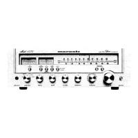
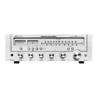
Exploded view and parts list for the front panel assembly of the Marantz receiver.
Specific parts list for the MR230 model, pertaining to front panel components.
Specific parts list for the MR235 model, pertaining to front panel components.
Exploded view and parts list for the lid (top cover) assembly of the Marantz receiver.
Specific parts list for the M1530 model, pertaining to lid components.
Parts list for specific regional models (MR230-N, MR235-U) of the lid assembly.
Exploded view and parts list for the rear panel assembly of the Marantz receiver.
Exploded view and parts list for the front chassis and other general parts.
Exploded view and parts list for assembled Printed Circuit Boards and related components.
List and diagrams of packing materials used for Marantz receiver models.
Detailed list of electrical components, including part numbers, descriptions, and specifications.
Performance specifications for the amplifier section, including power output and distortion.
Specifications for the preamplifier section, covering input sensitivity and frequency response.
Performance specifications for the AM and FM tuner sections, including sensitivity and selectivity.
General technical specifications including power requirements, dimensions, and weight.
| Power output | 30 watts per channel into 8Ω (stereo) |
|---|---|
| Total harmonic distortion | 0.1% |
| Input sensitivity | 2.5mV (MM), 150mV (line) |
| Output | 150mV (line) |
| Speaker load impedance | 4Ω to 16Ω |
| Semiconductors | 22 x diodes |
| Tuning range | FM, MW |