Do you have a question about the Marantz 2238B and is the answer not in the manual?
Lists essential test equipment and their specified uses for servicing the receiver.
Step-by-step guide for aligning the AM Intermediate Frequency stages.
Procedure for tuning and aligning the AM frequency range and tracking.
Steps for aligning the FM frequency range, tracking, and tuning meter.
Method for adjusting stereo separation for optimal FM reception.
Adjusting the FM muting sensitivity level.
Calibrating the Dolby level for FM signals.
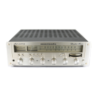
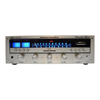
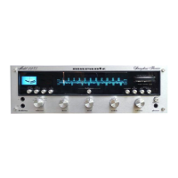
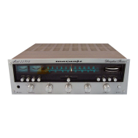
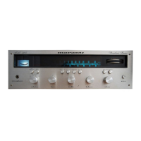
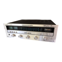
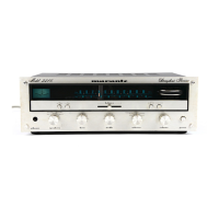
Identification of components and adjustment points on the front panel.
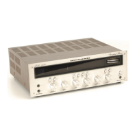
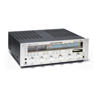
Location map for components on the top side of the main chassis.
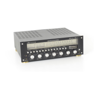
Identification of components and connectors on the rear panel.
Location map for components on the bottom side of the main chassis.
Schematic and component layout for the FM/AM tuner board.
Schematic and component layout for the dial lamp assembly.
Schematic and component layout for the DLB-1 socket assembly.
Schematic and component layout for the main amplifier and power supply.
Schematic and component layout for the tone amplifier board.
Schematic and component layout for the FM front end board.
Schematic and component layout for the equalizer amplifier board.
Wiring diagrams illustrating connections for US and Canadian models.
Wiring diagrams illustrating connections for the European model.
Detailed circuit diagrams for US and Canadian models.
Detailed circuit diagrams for the European model.
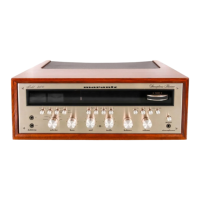
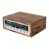
Diagram showing the assembly and parts of the receiver's cabinet.
Diagram showing the assembly and parts of the receiver's chassis.
Diagrams detailing the assembly of rear panels for different models.
| Power Output | 38 watts per channel into 8Ω (stereo) |
|---|---|
| Total Harmonic Distortion | 0.1% |
| Damping Factor | 45 |
| Input Sensitivity | 2.2mV (MM), 180mV (line) |
| Dimensions | 440 x 137 x 365mm |
| Speaker Load Impedance | 4Ω to 16Ω |
| Tuning Range | FM: 88MHz to 108MHz, AM: 520kHz to 1600kHz |