Do you have a question about the Marantz 2285 and is the answer not in the manual?
Procedure for aligning the AM Intermediate Frequency stage.
Aligns AM tuner for optimal reception across frequency bands.
Calibrates the AM signal strength meter for accurate readings.
Aligns FM tuner for optimal reception across frequency bands.
Optimizes stereo separation for FM broadcasts.
Aligns the FM muting circuit for proper operation.
Sets the Dolby FM tape output levels for accurate playback.
Aligns the DC offset for the main amplifier channels.
Adjusts the idle current for amplifier stages.
Adjusts phono amplifier clipping levels for optimal performance.
Shows how different circuit boards connect to each other.
Provides a high-level overview of the receiver's functional blocks.
Schematic and layout for the FM front end circuitry.
Schematic and layout for the AM tuner circuitry.
Schematic and layout for the FM IF amplifier circuitry.
Schematic and layout for the MPX stereo decoder board.
Schematic and layout for the Dolby level control board.
Schematic and layout for the phono preamplifier circuit.
Schematic and layout for the main power amplifier circuit.
Schematic and layout for the power supply unit.
Schematic and layout for the pre and tone control amplifier.
Schematic and layout for Dolby FM and tape monitor functions.
Schematic and layout for the function indicator lamps.
Schematic and layout for the dial illumination lamps.
Schematic and layout for the antenna muting circuit.
Schematic and layout for the filter amplifier circuit.
Schematic and layout for filter and loudness control circuits.
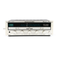
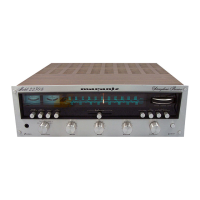
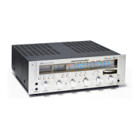
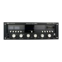
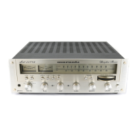
Identifies major components visible from the front of the unit.
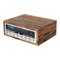
Identifies major components on the top of the chassis.
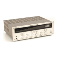
Identifies major components visible from the rear of the unit.
Identifies major components on the bottom of the chassis.
Identifies rear components for European model variants.
Identifies bottom chassis components for European model variants.
Illustrates the packaging components for shipping.
Shows the assembly of mechanical parts of the receiver.
| Power Output | 85 watts per channel into 8Ω (stereo) |
|---|---|
| Total Harmonic Distortion | 0.1% |
| Damping Factor | 60 |
| Input Sensitivity | 2.2mV (MM), 180mV (line) |
| Speaker Load Impedance | 4Ω to 16Ω |
| Tuning Range | FM, MW |
| Signal to Noise Ratio | 80dB (MM), 90dB (line) |