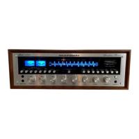
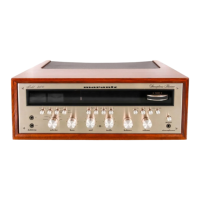
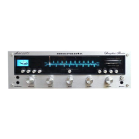
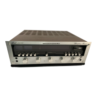
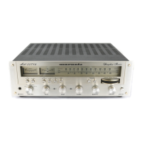
MARANTZ MODEL 2325 SERVICE MANUAL
INTRODUCTION
This service manual was prepared for use by Authorized Warranty Stations and contains
service information for the Marantz Model 2325 Stereophonic Receiver.
Servicing information and voltage date included in this manual are intended for use by the
knowledgeable and experienced technician only. All instructions should be read carefully. No
attempt should be made to proceed without a good understanding of the operation of the
receiver.
The parts list furnishes information by which replacement part may be ordered from the
Marantz Company. A belief description is included for parts which can be usually be obtained
through local suppliers.
1. SERVICE NOTES
As can be seen from the circuit diagram, the chassis of the Model 2325 consists of the
following units. Each unit mounted on a printed circuit board is drawn within bold dotted-line
block on the circuit diagram.
1. FM Front End ...................................................................... Mounted on P.W. Board P100
2. AM Tuner Unit.................................................................... Mounted on P.W. Board P150
3. FM IF Amplifier.................................................................. Mounted on P.W. Board P200
4. MPX Stereo Decoding Amplifier ......................................... Mounted on P.W. Board P300
5. Phono Amplifier .................................................................. Mounted on P.W. Board P400
6. Dolby Unit........................................................................... Mounted on P.W. Board P600
7. Power Amplifier................................................................... Mounted on P.W. Board P700
8. Power Supply and Protection Relay Circuit........................ Mounted on P.W. Board P800
9. FM Cal. ................................................................................ Mounted on P.W. Board PC01
10. Pre and Tone Amplifier ..................................................... Mounted on P.W. Board PE01
11. Buffer Amplifier................................................................. Mounted on P.W. Board PH01
12. 400Hz Tone ...................................................................... Mounted on P.W. Board PL01
13. 400Hz Tone, Tape 1 and 2 Tape Monitor Switch.............. Mounted on P.W. Board PS01
14. Tape Monitor Assembly..................................................... Mounted on P.W. Board PT01
15. Multipath, Hi Blend, FM Muting, Low Filter,
Hi Filter, Loudness, Main Speaker and
Remote Speaker......................................................................... Mounted on P.W. Board PU01
16. Function Lamp .................................................................. Mounted on P.W. Board PY01
17. Dial Lamp .......................................................................... Mounted on P.W. Board PZ01
2. AM TUNER
The AM Tuner section in the 2325 consists of one IC, including an RF amplifier, local
oscillator, mixer, IF amplifier, and detector, and three transistors, one of which forms a signal
strength indication amplifier and the other two form detected audio signal amplifier.
All components except the tuning capacitor and ferrite bar antenna are mounted on the
printed circuit board P150.
The AM signal induced in the ferrite bar antenna is fed to the RF amplifier input (Pin 12)
and amplified to the level required for overcoming conversion noises, thus giving good S/N
performance. The tuned circuit inserted in each of the output and input circuits of the RF
amplifier assures very high image and spurious rejection performance.
Thus the amplified and selected AM signal is then applied to one Mixer input (Pin 1).
While the local oscillator voltage is injected to the other Mixer input (Pin16) through a
capacitor C157. Then both AM signal and local oscillator output voltage are mixed and
converted into 455kHz intermediate frequency. The resulting IF signal is applied to the IF
transformer L153 consisting of one ceramic filter and two tuned circuits.
www.freeservicemanuals.info
Digitized in Heiloo Netherland