Do you have a question about the Marantz 2330 and is the answer not in the manual?
Overview of circuit boards within the Model 2330 receiver.
List of essential test equipment for servicing the Model 2330.
Step-by-step guide for aligning the AM tuner section.
Step-by-step guide for aligning the FM tuner section.
Procedure for aligning the Dolby FM decoder circuit.
Detailed steps for adjusting audio circuits and voltages.
Instructions for converting the unit to different power source voltages.
Schematic and component layout for the FM Front End.
Schematic and component layout for the AM Tuner.
Schematic and component layout for the Dolby FM Decoder.
Schematic and component layout for the Main Amplifier.
Schematic and component layout for the Power Supply/Relay board.
Schematic and component layout for the Pre and Tone Amplifier.
Schematic and component layout for the Buffer Amplifier.
Schematic and component layout for the Function Lamp board.
Schematic and component layout for the Dial Lamp board.
Schematic for Filter, Loudness, and Speaker Switches board.
Schematic for Tape Copy, MPX Noise, Multipath, and FM Muting Switches board.
Schematic for FM Balun and Muting Level board.
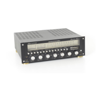
Component locations on the front cabinet for US/Canada models.
Component locations on the top chassis for US/Canada models.
Component locations on the rear cabinet for US/Canada models.
Component locations on the bottom chassis for US models.
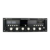
Component locations on the front cabinet for European models.
Component locations on the top chassis for European models.
Component locations on the rear cabinet for European models.
Component locations on the bottom chassis for European models.
Detailed exploded view of the receiver's mechanical components.
Exploded view illustrating packing materials for the unit.
Technical specifications for the amplifier and preamplifier sections.
Technical specifications for the FM and AM tuner sections.
Overall technical specifications including power requirements and dimensions.
| Power Output | 130 watts per channel into 8Ω (stereo) |
|---|---|
| Damping Factor | 60 |
| Input Sensitivity | 2.2mV (MM), 180mV (line) |
| Tuning Range | FM, MW |
| Speaker Load Impedance | 4Ω to 16Ω |