8
-----
----
.-.•-:.-.
3. Turn on MUTING pushswitch.
Shift
the
FM
signal generator frequency
to
plus
and
minus
and
note both plus
and
minus shifted frequencies at which undesirable audio
side
responses
are
muted out. Adjust the R487
so
that
the
same
shifted frequencies mute the undesirable
side
response.
11.
AUDIO ADJUSTMENT
1.
Connect a
VTVM
to J613(+)
and
J629(-)
and
adjust the trimming resistor R628 until the
VTVM
reads
10mV
DC.
For the other channel connect the
VTVM
to
J614(+)
and
J630(-)
and adjust the R629
for
the
same
reading.
2.
Connect a
VTVM
to
J629(+)
and
J623(-)
and
adjust the trimming resistor R613
until
the
VTVM
reads
OV
DC.
For the other channel connect the
VTVM
to
J630(+) and
J624(-)
and adjust the R614
until
the
VTVM
reads
OV
DC.
12.
AUTOMATIC VOLTAGE REGULATOR ADJUSTMENT
Connect a
VTVM
to
J802(+)
and
J820(-)
and
adjust R809
until
the
VTVM
reads
35 V
under no
signal
condition.
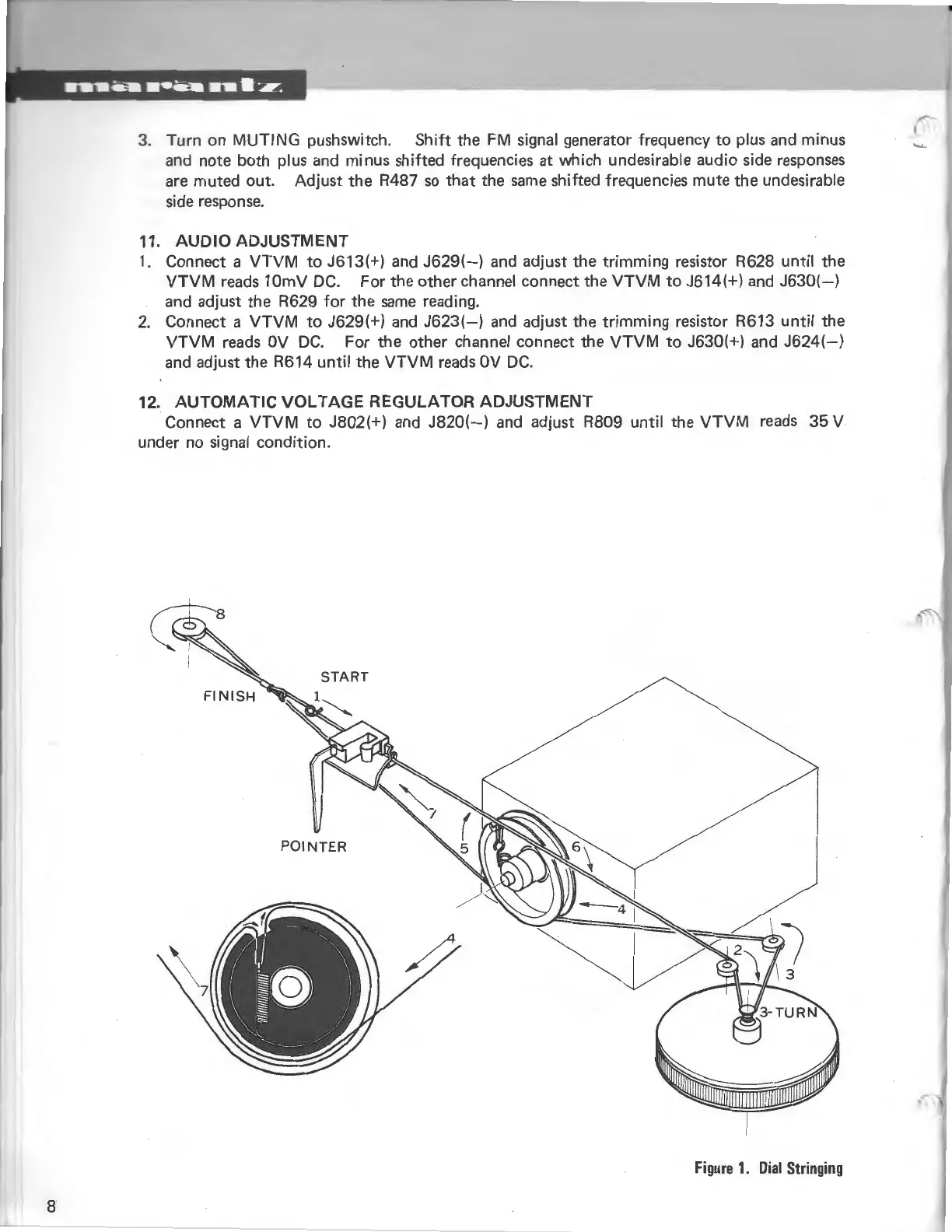
START
POINTER
Figure
1.
Dial
Stringing