INTRODUCTION
This service manual
was
prepared
for
use
by Authorized Warranty Stations and contains
service information
for
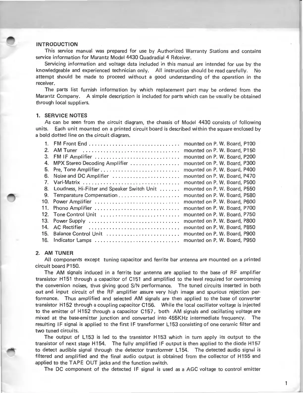
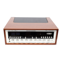
Marantz Model 4430 Quadradial 4
RE!ceiver.
Servicing information
and
voltage data included in this manual
are
intended
for
use
by the
knowledgeable
and
experienced technician only.
All
instruction should
be
read
carefully. No
attempt
should
be
made
to
proceed
without
a good understanding
of
the operation in the
receiver.
The parts list furnish information by which replacement part may
be
ordered
from
the
Marantz Company. A simple description
is
included
for
parts which
can
be
usually
be
obtained
through local suppliers.
1.
SERVICE NOTES
As
can
be
seen
from
the
circuit
diagram, the
chassis
of
Model 4430 consists
of
following
units.
Each
unit
mounted on a printed
circuit
board
is
described
within
the square enclosed by
a bold dotted line on the
circuit
diagram.
1.
FM
Front
End . . . . . . . . . . . . . . . . . . . . . . . . . . . . . . . mounted on
P.
W.
Board, P100
2.
AM Tuner . . . . . . . . . . . . . . . . . . . . . . . . . . . . . . . . . mounted on
P.
W.
Board, P150
3.
FM
IF
Amplifier
. . . . . . . . . . . . . . . . . . . . . . . . . . . . . mounted on
P.
W.
Board, P200
4.
MPX Stereo Decoding
Amplifier
. . . . . . . . . . . . . . . . . mounted on
P.
W.
Board, P300
5.
Pre,
Tone
Amplifier..
. . . . . . . . . . . . . . . . . . . . . . . . . mounted
on
P.
W.
Board, P400
6.
Noise and
DC
Amplifier
. . . . . . . . . . . . . . . . . . . . . . . mounted on
P.
W.
Board, P470
7.
Vari-Matrix . . . . . . . . . . . . . . . . . . . . . . . . . . . . . . . . . mounted on
P.
W.
Board, P500
8.
Loudness, Hi-Filter
and
Speaker Switch
Unit
. . . . . . . mounted on
P.
W.
Board, P550
9.
Temparature Compensation . . . . . . . . . . . . . . . . . . . . . mounted on
P.
W.
Board, P580
10. Power
Amplifier
. . . . . . . . . . . . . . . . . . . . . . . . . . . . . mounted on
P.
W.
Board, P600
11. Phono
Amplifier
. . . . . . . . . . . . . . . . . . . . . . . . . . . . . mounted
on
P.
W.
Board, P700
12. Tone Control
Unit
...........................
mounted on
P.
W.
Board, P750
13. Power Supply . . . . . . . . . . . . . . . . . . . . . . . . . . . . . . . mounted on
P.
W.
Board, P800
14. AC Rectifier . . . . . . . . . . . . . . . . . . . . . . . . . . . . . . . mounted on
P.
W.
Board, P850
15. Balance Control
Unit
. . . . . . . . . . . . . . . . . . . . . . . . . mounted on
P.
W.
Board, P900
16. Indicator Lamps . . . . . . . . . . . . . . . . . . . . . . . . . . . . . mounted on
P.
W.
Board, P950
2.
AM
TUNER
All
components except tuning capacitor
and
ferrite bar antenna
are
mounted on a printed
circuit
board P150.
The
AM
signals induced in a ferrite bar antenna
are
applied
to
the
base
of
RF
amplifier
transistor H151 through a capacitor
of
C151
and amplified
to
the level required
for
overcoming
the conversion
noises,
thus giving good SIN performance. The tuned circuits inserted in both
out
and
input
circuit
of
the
RF
amplifier
assure
very high
image
and
spurious rejection per-
formance. Thus amplified and selected AM signals
are
then applied
to
the
base
of
converter
transistor H152 through a coupling capacitor C156. While
the local oscillator voltage
is
injected
to
the emitter
of
H 152 through a capacitor C157,
both
AM
signals
and
oscillating voltage
are
mixed at the base-emitter junction
and
converted into 455KHz intermediate frequency. The
resulting IF signal
is
applied
to
the
first
IF transformer L 153 consisting
of
one ceramic
filter
and
two
tuned circuits.
The
output
of
L153
is
led
to
the transistor H 153 which in
turn
apply its
output
to
the
transistor
of
next
stage
H154. The
fully
amplified IF
output
is
then applied
to
the diode H157
to
detect audible signal through the detector transformer L154. The detected audio signal
is
filtered and amplified and the final audio
output
is
obtained
from
the collector
of
H 155
and
applied
to
the
TAPE
OUT
jacks and the function switch.
The
DC
component
of
the detected IF signal
is
used
as
a AGC voltage
to
control emitter