•
•
SERVICING
HINTS
ESD
/-
~
All
ICs
and many other semi-conductors are susceptible
to electrostatic discharges
(ESD).
Careless handling during repair can drastically reduce life
expectancy.
When
repairing, make sure that you are connected via a
wrist wrap with resistance to the same potential as the
chassis of the set. Keep components and aids also at
the same potential.
The disc should always rest properly on the turntable.
To
achieve this a disc hold-down has been mounted
in
a
bracket
of
the tray mechanism.
lf
the tray mechanism has to
be
disassembled
lor
servicing, a separate disc hold-down should
be
used.
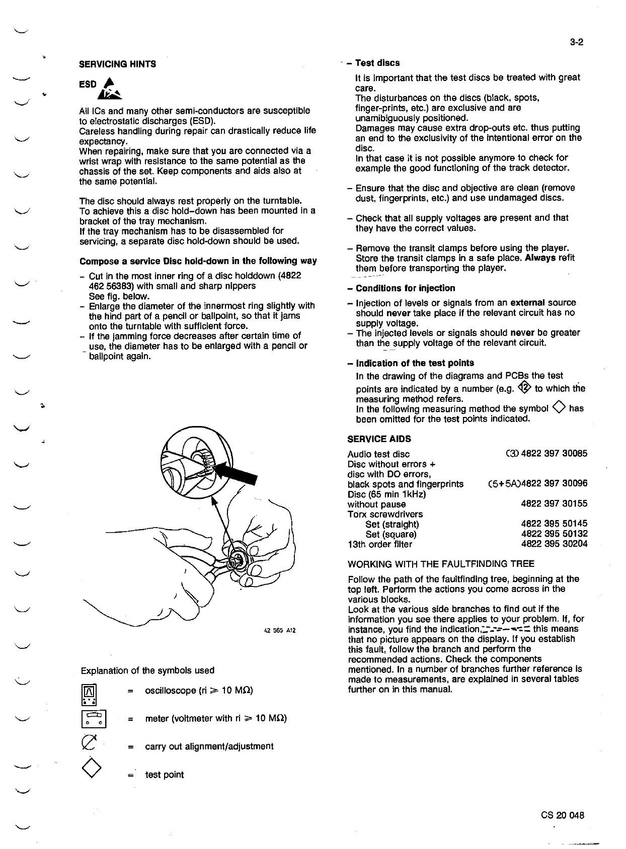
Compose
a
service
Disc
hold-down
in the lollowing
way
- Cut in the most inner ring
of
a disc holddown (4822
462 56383) with small and sharp nippers
See
fig. below.
- Enlarge the diameter of the innermost ring slightly with
the hind part of a pencil or ballpoint, so that it jams
onto the turntable with sufficient force.
-
lf
the jamming force decreases alter certain time
of
_
use,
the diameter has to
be
enlarged with a pencil
or
ballpoint again.
~)
42
565
A12
Explanation of the symbols used
liffil
181
~
e
◊
oscilloscope (ri
;;,,
10
MQ)
= meter (voltmeter with
ri
;;,,
1 O MQ)
= carry out alignment/adjustment
test point
3-2
- - Test discs
lt
is important that the test discs
be
treated with great
care.
The disturbances on the discs (black, spots,
finger-prints, etc.) are exclusive and are
unamibiguously positioned.
Damages may cause extra drop-outs etc. thus putting
an
end to the exclusivity
of
the intentional error on the
disc.
In
that case
it
is not possible anymore to check
lor
example the good functioning
of
the track detector.
- Ensure that the disc and objective are clean (remove
dust, fingerprints, etc.) and use undamaged discs.
- Check that all supply voltages are present and that
they have the correct values.
- Remove the transit clamps before using the player.
Store the transit clamps in a safe place.
Always refit
thern_before transporting the player.
-
Conditions
for injection
- lnjection
of
levels or signals !rom
an
external source
should
never take place
il
the relevant circuit has no
supply voltage.
- The injected levels or signals should
never
be
greater
than
th_e
_supply voltage
of
the relevant circuit.
- lndication of the test
points
In
the drawing
of
the diagrams and PCBs the test
points are indicated by a number (e.g.
~
to which the
measuring method refers .
In the following measuring method the symbol
◊
has
been omitted
lor
the test points indicated.
SERVICE
AIDS
Audio test disc
Disc without errors
+
disc with
DO
errors,
black spots and fingerprints
Disc
(65
min 1 kHz)
without pause
Torx screwdrivers
Set (straight)
Set (square)
13th order filter
(3)
4822 397 30085
(5+
5A)4822 397 30096
4822 397 30155
4822 395 50145
4822 395 50132
4822 395 30204
WORKING
WITH
THE FAULTFINDING TREE
Follow the path
of
the faultlinding tree, beginning at the
top lelt. Perform the actions you come across in the
various blocks.
Look at the various side branches to find out
if
the
information you see !here applies to your problem. lf,
lor
instance, you find the indication,:.----=--~-:= this means
that no picture appears on the display.
lf
you establish
this fault, follow the branch and perform the
recommended actions. Check the components
mentioned.
In
a number
of
branches further reference is
made to measurements, are explained
in
several tables
further on in this manual.
es 20 048