1-1
' 1. EXPLANATION OF THE LAYOUT OF THE
TABLE OF CONTENTS PER PAGE
0
0
DOCUMENTATION
The documentation consists
of
chapters.
Chapter
The number
of
the chapter is indicated by the first digit
of
the page number.
The second digit
of
the page number
is
the sequence
numbering.
lf
modifications
or
supplements require new
supplementary
or
replacement pages, the page
number is extended with a third part:
A digit behind the page number indicates that
il
concerns a supplementary page.
A replacement page
is
indicated by a letter behind the
page number.
Example
3-6
3-6-1
3-6-a
is page 6
of
chapter 3
is a supplementary page behind page 3-6
is the replacement page
of
page 3-6 (so
page 3-6 can be removed
trom
the
documentation).
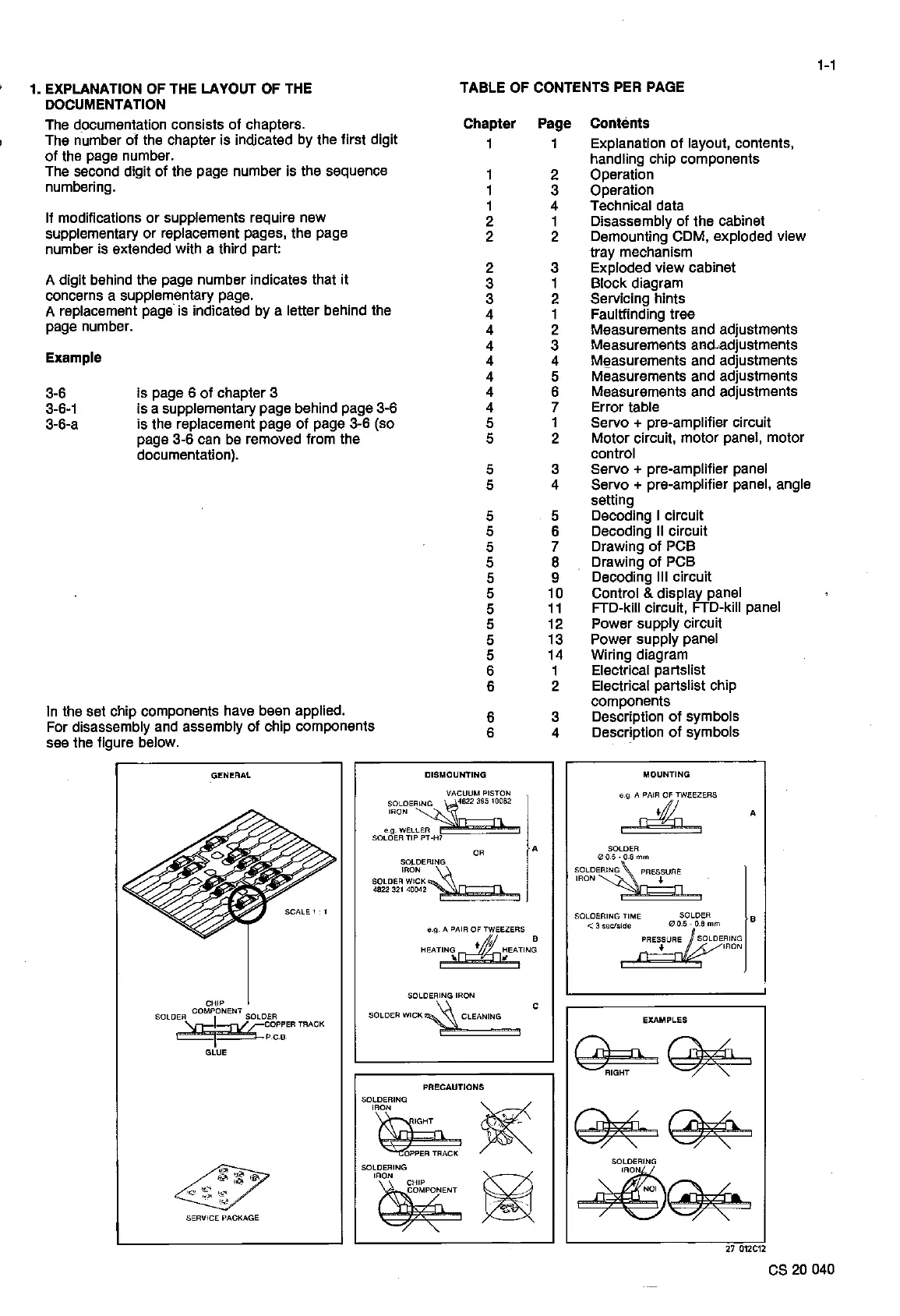
In
the set chip components have been applied.
For disassembly and assembly
of
chip components
see
the figure below.
1
1
1
1
2
2
2
3
3
4
4
4
4
4
4
4
5
5
5
5
5
5
5
5
5
5
5
5
5
5
6
6
6
6
GENERAL
DISMOUNTING
VACUUM PISTON
socoe~"
lRON
n------n
e.g. WELLER
SOLOER
TIP
PT-H7
os
SOLDERING
IRON~
SOLDER WICK
4822
321
40042W7
A
osAa,~mss
B
HEATIN~~~EATING
1 1
CHIP
COMPONENT
SOLOEA~
SOLDER
?YcCOPP.ER
TRACK
i P.C.B
GLUE
SERVICE PACKAGE
SOLDERING IRON
SOLDER WICK
~
CLEANING
PRECAUTIONS
SOLDERING
'~
~
SOLDERING
IRON
C
Page
1
2
3
4
1
2
3
1
2
1
2
3
4
5
6
7
1
2
3
4
5
6
7
8
9
10
11
12
13
14
1
2
3
4
Contènts
Explanation
of
layout, contents,
handling chip components
Operation
Operation
Technica! data
Disassembly
of
the cabine!
Demounting CDM, exploded view
tray mechanism
Exploded view cabine!
Black diagram
Servicing hints
Faultfinding tree
Measurements and adjustments
Measurements and-adjustments
M~asurements and adjustments
Measurements and adjustments
Measurements and adjustments
Error table
Servo
+ pre-amplifier circuit
Motor circuit, motor panel, motor
control
Servo + pre-amplifier panel
Servo
+ pre-amplifier panel, angle
setting
Decoding I circuit
Decoding Il circuit
Drawing
of
PCB
Drawing
of
PCB
Decoding
111
circuit
Control & display panel
FTD-kill circuit, FTD-kill panel
Power supply circuit
Power supply panel
Wiring diagram
Electrical partslist
Electrical partslist chip
components
Description
of
symbols
Description
of
symbols
MOUNTING
SOLOER
0O.5-O.Smm
SOLDERING PRESSURE
IRON
,J-
SOLDERING TIME SOLDER
< 3
sec/s,de
0 0.5 -
O.B
mm
PRESSURE SOLDERING
♦
IRON
EXAMPLES
A
B
27
012C12
es
20
040