11
2101
E 7
2102
E 7
2103
C 7
2104
B 8
2105
D 8
2106
C 8
A 2107 B 8
2108
D 8
2109
B 7
2110
D 6
2111
E 6
2112
E 7
2113
C 7
2114
C 5
2117
C 6
2135
E 4
B 2136 E 7
2137
D 2
2138
E 2
2139
E 2
2140
E 1
2141
D 5
2142
E 5
2150
D 4
2151
D 4
2152
C 3
C
2153 C 3
2154
C 3
2155
D 3
2156 8 3
2159
E 4
2160
D 5
2200
A i
2202 D 1
2203
C 2
2204
C 1
2205
E 2
D
3101
D 5
3102
0 8
3103
E 7
3104
8 5
3105
C 6
3106
C 6
3107
A 8
3108
A 8
3109
D 7
3110 D 6
E
31
l l C 8
3112 D 6
3113
C 7
3114
B 7
3115
D 7
3116
C 5
3119
D 7
3135
D 4
3135
E 4
3137
D 6
3138
E 2
3139
E 4
3140
D 2
3141
E 4
3142
E 4
3143
E 4
3144
D 4
3145 D 2
11
11
1 1
PRS.02853
r-
-,
1
C,
'}
,,1
1.._
.J
1 1
1 1
1 1
r--,
--,
1 ° \ 1 "1
'----
_--1
r~, +
I \
I
C•
t=.-::.-:
'
1 1
l~J
3146
· 3150
3151
3152
3153
3154
3155
3156
3157
3158
3159
3160
3161
3162
3163
3166
3167
3191
3192
3193
3201
3202
3204
3205
3206
3207
3208
3209
3210
3211
3701
3702
3704
3705
3706
3709
3710
3712
3713
3714
3716
3717
3718
3720
3721
3722
3723
3725
5101
6103
6104
6105
6107
6108
6109
6110
6111
6112
6118
6119
D 3
B 4
C 4
C 2
C 2
D 2
C 3
C 2
C 3
B 2
E 5
E 5
E 3
C 3
E 5
D 3
D 3
8 3
B 6
B 5
A l
E l
E l
D l
D l
B 2
B 2
B 2
D 1
D 2
D 7
A 2
D 7
8 4
C 4
B 4
C 2
E 4
E 3
B 3
E 3
E 3
D 4
D 6
D 6
B 6
A l
C !
D 7
0 !
E 3
C 4
C 3
C 5
C 2
8 i
C !
B 2
E 5
E 5
OBJECTIVE
----Q
11
ARM~I
0
ARM
BEARING 1 1 /
PLATE
~
~:::-1,
c'l-~-F-
ADJUST SCREWS
r:;-,
-
I 1
(
c,
t
-::.-::
:Q
1 1
\..:.J
-
- r;-,
1 \
(
()
t==ü
\ 1
Fig.
3
-
L~J
38
692
A12
OBJE:CTIVE
DISC
ITRANSPAAENTl
4822
395
90204
L1
L60
A12
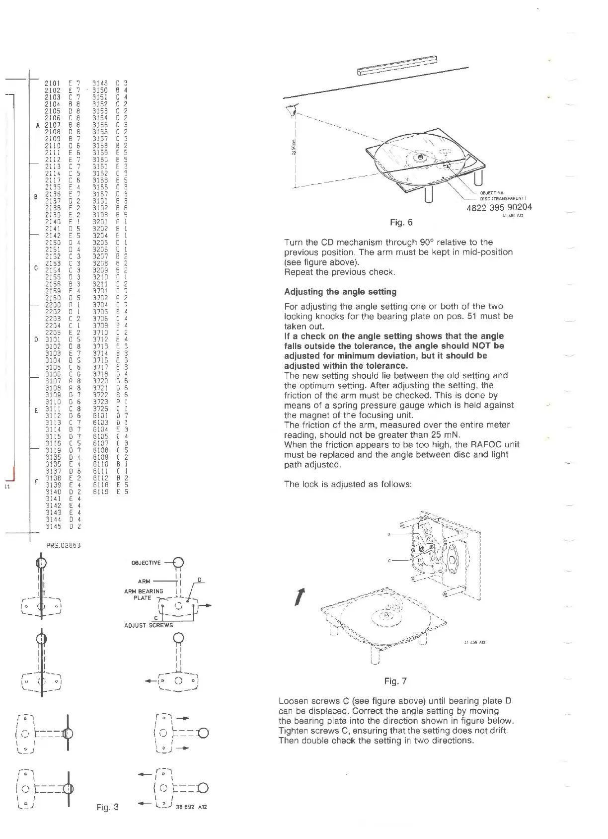
Fig. 6
Turn the CD mechanism through
90°
relativa to the
previous position. The arm must
be
kept in mid-position
(see figure above).
Repeat the previous check.
Adjusting the angle setting
For adjusting the angle setting one
or
both
of
the
two
locking knocks tor the bearing plate on pos.
51
must be
taken out.
lf a check on the angle setting shows that
the
angle
falls outside the tolerance, the angle should NOT be
adjusted for minimum deviation, but it should be
adjusted within the tolerance.
The new setting should lie between the
old
setting and
the optimum setting. After adjusting the setting, the
friction
of
the arm must be checked. This is done by
means
of
a spring pressure gauge which is held against
the magnet
of
the focusing unit.
The friction
of
the arm, measured over the entire meter
reading, should
not
be greater than
25
mN.
When the friction appears to be
too
high, the RAFOC unit
must be replaced and the angle between disc and light
path adjusted.
The loek
is
adjusted as follows:
1
Fig. 7
Loosen screws C (see figure above) until bearing plate D
can be displaced. Correct the angle setting by moving
the bearing plate into the direction shown in figure below.
Tighten screws C, ensuring that the setting does
not
drift.
Then double check the setting
in
two directions.