EasyManua.ls Logo

Marantz DR700 User Manual

Marantz DR700
52 pages
To Next Page IconTo Next Page
Page #1 background imageLoading...
Page #1 background image
Question and Answer IconNeed help?

Do you have a question about the Marantz DR700 and is the answer not in the manual?

Marantz DR700 Specifications

General IconGeneral
BrandMarantz
ModelDR700
CategoryCD Player
LanguageEnglish

Summary

Main Unit Service

Introduction and Overview

Explains product versions, opening, and basic functionality.

Technical Specifications

Details operational parameters and disc compatibility.

Safety Warnings and Precautions

Covers ESD, laser, and general safety advice.

Service Hints and Tools

Provides repair guidance and necessary tools.

Test Programs

Dealer and Service Diagnostics

Explains built-in dealer and service diagnostic tests.

Dismantling Instructions

CDR630 Disassembly Steps

Step-by-step guide for CDR630 disassembly.

Dismantling Instructions

DR700 Disassembly Steps

Step-by-step guide for DR700 disassembly.

Block Diagrams

CDR630 System Architecture

Illustrates the architecture of the CDR630.

Block Diagrams

DR700 System Architecture

Illustrates the architecture of the DR700.

Signal Names and Abbreviations

Signal Definitions and Usage

Lists and defines signals used in the system.

Faultfinding Guide

General Troubleshooting Flowchart

Outlines the primary diagnostic steps.

Disc-Specific Faultfinding

CDDA Disc Playback Troubleshooting

Steps for CDDA playback issues.

Disc-Specific Faultfinding

CD-R Disc Recording Troubleshooting

Steps for CD-R recording issues.

Disc-Specific Faultfinding

CD-RW Disc Erasing Troubleshooting

Steps for CD-RW erasing problems.

Display Panel Measurements

Voltage and Control Line Checks

Details measurement procedures for display functionality.

Mains Transformer Description

Transformer Specifications and Variants

Details voltage outputs and current ratings.

Wiring Diagrams

CDR630 and DR700 Wiring Schematics

Illustrates internal connections for both models.

Schematic Diagram and Parts Location

Power Supply Circuit Diagram

Detailed circuit diagram for the power supply board.

Display and Control Circuitry

CPU and Display Controller Logic

Shows the integrated circuit layout for display functions.

Board Layouts

Headphone and Level Board Layouts

PCB component placement for headphone and level control.

Connector Board Details

DR700 Connector Board Layout

Component placement for DR700 input/output connectors.

Connector Board Details

CDR630 XLR Connector Board

Component placement for CDR630 XLR connections.

Connector Board Details

CDR630 Cinch Connector Board

Component placement for CDR630 Cinch connections.

Exploded View and Parts List

CDR630 Component Breakdown

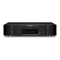
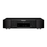
Visual representation and part numbers for CDR630.

Exploded View and Parts List

DR700 Component Breakdown

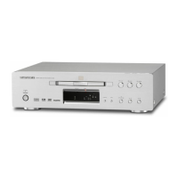
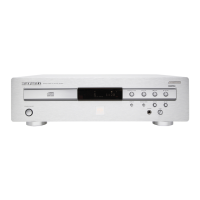
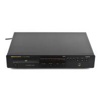
Visual representation and part numbers for DR700.

Electrical Parts List

Component Part Numbers

Lists electronic components for various boards.

CDR Module Service Manual

Module Block Diagram

System architecture for the CDR module.

Module Parts Location

Component layout for the CDR module's main board.

Module Exploded View and Parts List

Lists components for the CDR module assembly.

Repair Procedure

Central Repair Process

Guidelines for returning defective CDR modules.

Related product manuals