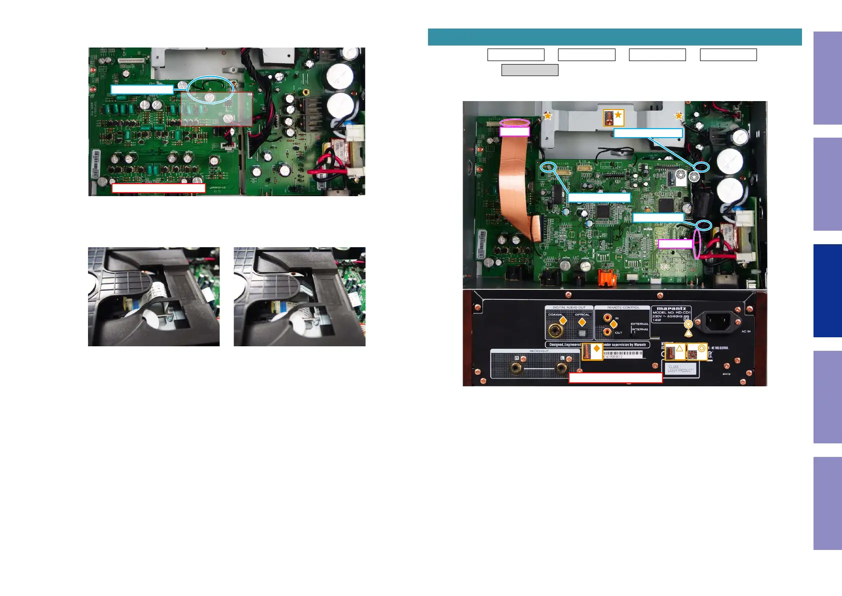
(3) Adjust the STYLE PIN of the AUDIO OUTPUT PCB when assembling the CD mecha.
Keep the FFC away from area "A".
(4) Make sure that the FFC does not enter the position shown in the "NG gure" when assembling the
CD mecha.
STYLE PIN
AUDIO OUTPUT PCB
A
NG OK
Proceeding : SIDE PANEL → TOP CABINET → FRONT ASSY → MECHA ASSY
→ MAIN PCB
(1) Remove the screws. Remove the PCB HOLDER. Remove the CORD HOLDER. Remove the STYLE PIN
and connectors. Remove the FFC.
5. MAIN PCB
↑Shooting direction: A↑
x3
x1
x1
x1
x2
FFC
CN2801
CORD HOLDER
PCB HOLDER
STYLE PIN
24
Caution in
servicing
Electrical Mechanical Repair Information Updating