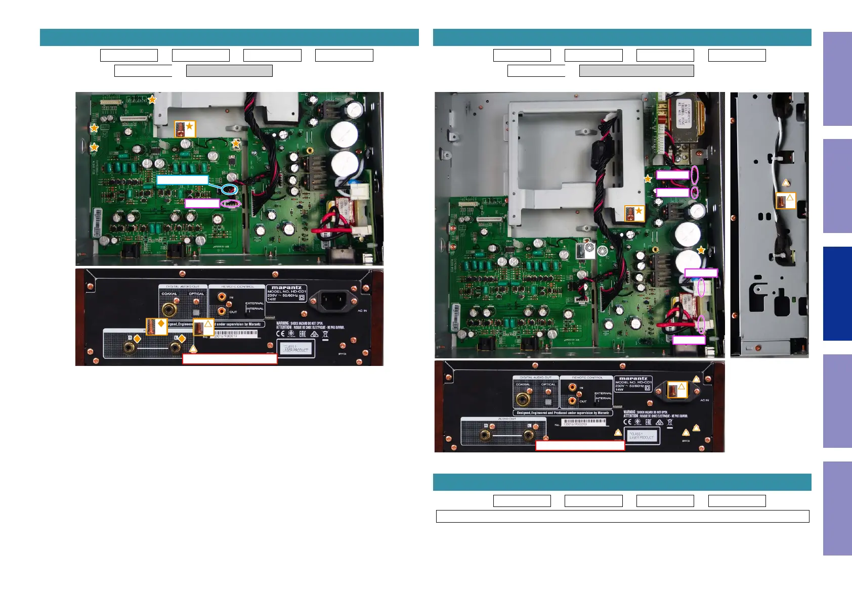
Proceeding : SIDE PANEL → TOP CABINET → FRONT ASSY → MECHA ASSY
→ MAIN PCB → AUDIO OUTPUT PCB
(1) Remove the screws. Remove the STYLE PIN. Remove the connector.
6. AUDIO OUTPUT PCB
↑Shooting direction: A↑
x2
x1
x4
CN3504
STYLE PIN
Proceeding : SIDE PANEL → TOP CABINET → FRONT ASSY → MECHA ASSY
→ MAIN PCB → POWER and SUP-POWER PCB
(1) Remove the screws. Remove the connector.
Proceeding : SIDE PANEL → TOP CABINET → FRONT ASSY → TRANS
See "EXPLODED VIEW" for instructions on removing the transformer (TRANS).
7. POWER and SUP-POWER PCB
↑Shooting direction: A↑
x4
x2
x1
x1
CN3903
CN3902
CN3901
CN3904
8. TRANS
25
Caution in
servicing
Electrical Mechanical Repair Information Updating