76
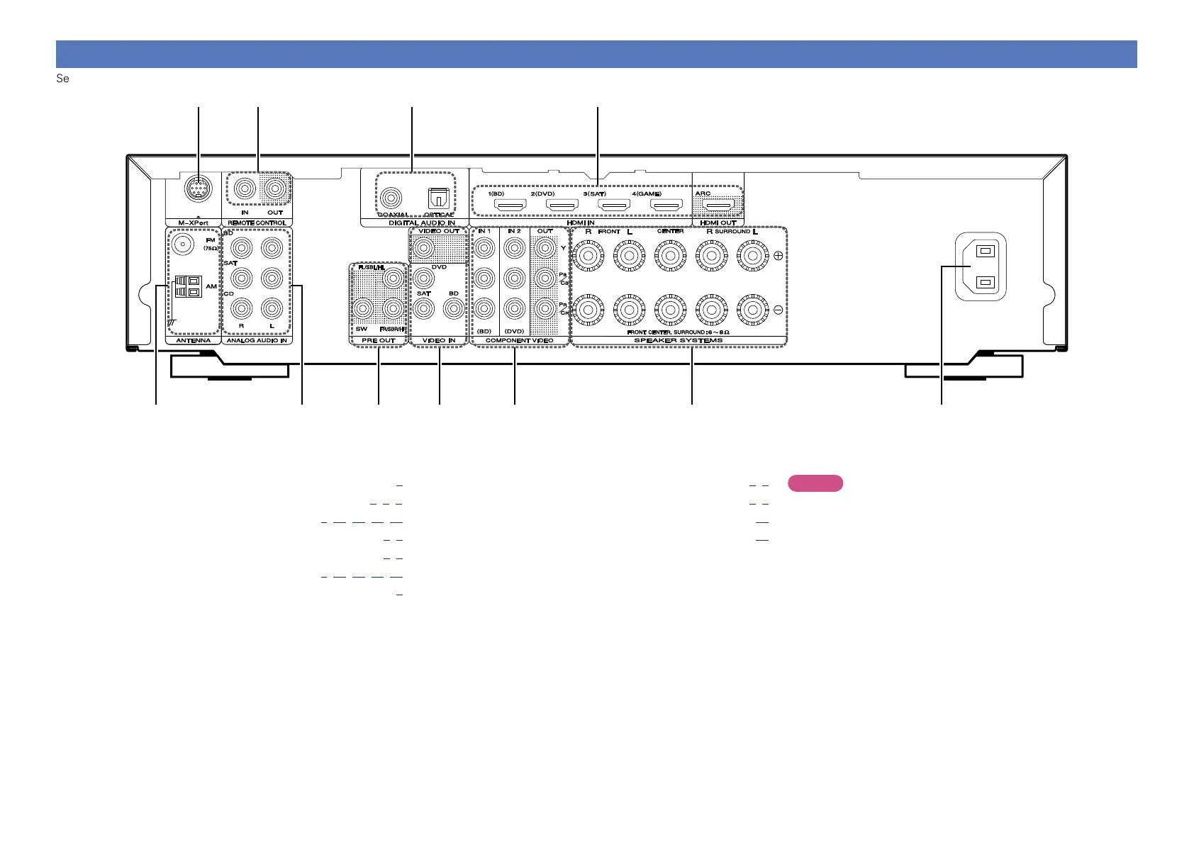
Rear panel
See the page indicated in parentheses ( ).
q w e r t y u
o
Q0Q1 i
q FM/AM antenna terminals ······················································· (9)
w Analog audio connectors ·················································· (7, 8, 9)
e PRE OUT connectors ································· (C 6, 31, 32, 33, 34)
r VIDEO connectors ································································· (7, 8)
t COMPONENT VIDEO connectors ········································· (7, 8)
y Speaker terminals ····································· (C 6, 31, 32, 33, 34)
u AC inlet (AC IN) ·································································· (C 5)
i HDMI connectors ··························································· (C 3, 6)
o Digital audio connectors ······················································· (7, 9)
Q0 REMOTE CONTROL connectors ············································· (37)
Q1 M-XPort connector ·································································· (10)
NOTE
Do not touch the inner pins of the connectors on the rear panel.
Electrostatic discharge may cause permanent damage to the unit.