2. DC Offset Voltage Adjustment
Adjustment Procedure
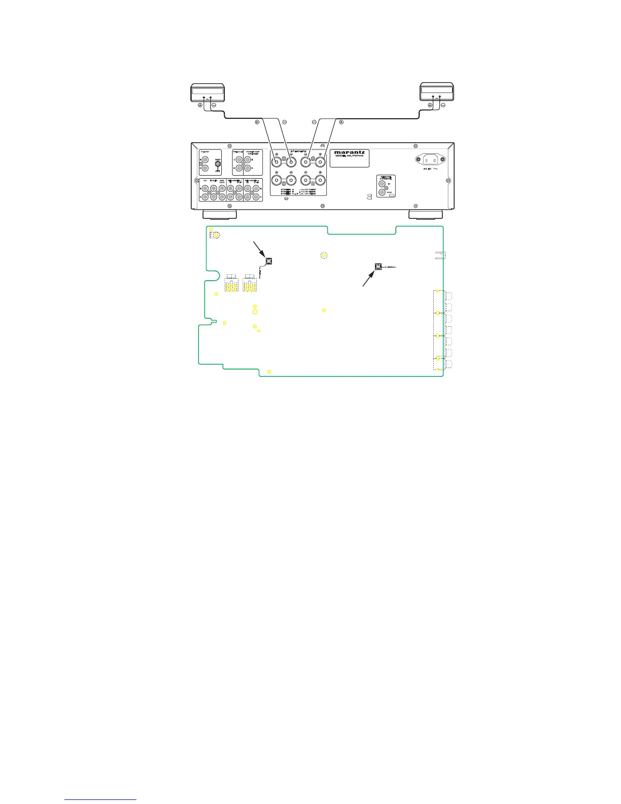
Set the power voltage to rated voltage for this adjustment.
Before turning on the power, Insert Digital Voltage Meter 1.
between the SPEAKERS SYSTEM A (L CH) "+" and "-".
Insert Digital Voltage Meter between the SPEAKERS
SYSTEM A (R CH) "+" and "-".
Adjust the VOLUME to MIN.2.
Turn on the power. Then turn the SPAKERS knob to A. 3.
Adjustment is started immediately after a speaker relay
turns on.
First L CH is adjusted. 4.
The variable resistor R639 on P101 is turned with
adjustment driver, and the Digital Voltage Meter is
adjusted to "0 mV ± 3 mV".
Then, R CH is adjusted. 5.
The variable resistor R640 on P101 is turned with
adjustment driver, and the Digital Voltage Meter is
adjusted to "0 mV ± 3 mV".
NOTE : DC offset voltage drops when turn the semi-fixed
resistor (R639 and R640) clockwise. DC offset
voltage rises when turn the semi-fixed resistor un-
clockwise. Please turn it slowly, because value of
Digital Voltage Meter changes slowly.
Although after-adjustment DC offset voltage has some 6.
change, Please check that the range of DC offset voltage
between L ch (R ch) "+" and L ch (R ch) "-" terminal of
SPEAKERS SYSTEM A is "0 mV ± 20 mV". CHART OF
FACTORY MODE
2. DC Offset Voltage Adjustment
調整手順
調整時は必ず電源電圧を定格電圧に合わせてください。
電源をONする前にリアパネルのSPEAKERS SYSTEM A1.
のL CHおよび、R CHそれぞれの"+"端子と"-"端子間にデジ
タルボルトメーターを接続します。
ボリュームをMINにセットします。2.
電源を投入し本体前面のSPEAKERSノブを回し、Aにしま3.
す。
スピーカーリレーがONした後に調整を開始します。
最初にL CHを調整します。 4.
P101基板の半固定抵抗R639を調整ドライバーで回し、L
CHスピーカー出力端子に接続したデジタルボルトメーター
の電圧が"0 mv ± 3 mV"以内になるように調整します。
次にR CHを調整します。 5.
P101基板の半固定抵抗R640を調整ドライバーで回し、R
CHスピーカー出力端子に接続したデジタルボルトメーター
の電圧が"0 mv ± 3 mV"以内になるように調整します。
注意 : 半固定抵抗(R639、R640)を時計回りに回すと、DCオ
フセット電圧は減少し、反時計回りに回すと増加しま
す。DCオフセット電圧の値は非常にゆっくりと増減し
ますので、半固定抵抗はゆっくりと回してください。
調整後DCオフセット電圧は多少の変動がありますが、 6.
SPEAKERS SYSTEM AのL CHおよび、R CHそれぞれ
の"+"端子と"-"端子間のDCオフセット電圧は"0 mV ± 20
mV"の範囲であることを確認してください。
 Loading...