EasyManua.ls Logo

Marantz PM8000 Service Manual

Marantz PM8000
29 pages
To Next Page IconTo Next Page
Page #1 background imageLoading...
Page #1 background image
Integrated amplifier
TABLE OF CONTENTS
SECTION PAGE
1. SPECIFICATIONS ...................................................................................................................................... 1
2. TEST EQUIPMENT REQUIRED SERVICING ........................................................................................... 2
3. IC INFORMATIONS.................................................................................................................................... 3
4. BLOCK DIAGRAM ...................................................................................................................................... 5
5. WIRING DIAGRAM..................................................................................................................................... 7
6. SCHEMATIC DIAGRAM AND PARTS LOCATION (PARTS SIDE) ........................................................... 9
7. EXPLODED VIEW AND PARTS LIST ...................................................................................................... 33
8. IDLING CURRENT AND DC OFFSET VOLTAGE ALIGNMENT ............................................................. 34
9. ELECTRICAL PARTS LIST ...................................................................................................................... 35
Service
Manual
PM7000 /N1B, /N1G, /U1B
PM8000 /N1B, /N1G, /F1B, /F1N
Please use this service manual with referring to the user guide (D.F.U) without fail.
R
- PM7000 / PM8000 -
276W855010 ACT
3120 785 22011
First Issue:1999.09
PM7000/8000
All manuals and user guides at all-guides.com
all-guides.com

Other manuals for Marantz PM8000

Question and Answer IconNeed help?

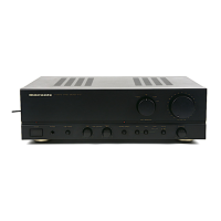
Do you have a question about the Marantz PM8000 and is the answer not in the manual?

Marantz PM8000 Specifications

General IconGeneral
Damping Factor100
Input Sensitivity2.5 mV (MM), 200 mV (line)
Frequency Response5Hz - 50kHz
Input Impedance47 kOhms (line)
Power Output70 watts per channel into 8 ohms (20 Hz - 20 kHz)

Summary

Specifications

Power Output

Details RMS and DIN power ratings for different operation modes.

IHF Dynamic Power

Specifications for IHF dynamic power output.

Input Specifications

Input sensitivity and signal-to-noise ratio for various inputs.

General Specifications

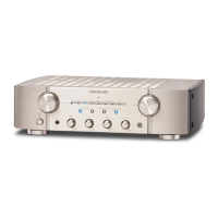
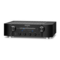
Includes dimensions, weight, power requirements, and accessories.

Test Equipment Required for Servicing

IC Informations

Microprocessor TMP47C200BM Block Diagram

Block diagram and pin functions of the main microprocessor.

Block Diagram

Wiring Diagram

Schematic Diagram and Parts Location

Function & Tape In/Out Circuit

Schematic for input/output and tape functions.

Power Circuit

Schematic detailing the power supply stages.

Front Circuit

Schematic for front panel controls and indicators.

Main Circuit

Schematic of the main amplification stages.

Tone Circuit

Schematic for bass and treble control sections.

SPK SW Circuit

Schematic for speaker switching and headphone connections.

Encoder Circuit

Schematic for the encoder signal processing.

Volume Control Circuit

Schematic for the motorized volume control system.

Board Assembly Drawings

Visual layout of components on various circuit boards.

Exploded View and Parts List

Exploded View

Diagram showing physical component layout for assembly.

Idling Current and DC Offset Voltage Alignment

Quiescent Current Adjustment

Procedures for setting idle current for Class AB and A operation.

DC Offset Voltage Alignment

Procedure to adjust DC offset at speaker terminals.

Electrical Parts List

Common Parts Codes

Definitions and conventions for component part codes.

Resistors

List of resistor types, values, and specifications.

Capacitors

List of capacitor types, values, and specifications.

Semiconductors

List of semiconductor components and their part numbers.

Miscellaneous Parts

List of other components like switches and connectors.

Related product manuals