Do you have a question about the Marantz PM8005 and is the answer not in the manual?
Guide to using the service manual, including search functions and schematic navigation.
Crucial safety information for servicing, including electric shock, disassembly, and part handling.
Details on power output, distortion, input sensitivity, tone control, and power requirements.
Step-by-step instructions for disassembling major assemblies like the front panel, heat sink, and PCBs.
Procedures for entering service mode and understanding protection circuit operation (PROT_1/PROT_2).
Procedures for microprocessor replacement and critical adjustments like DC offset and idling current.
Troubleshooting steps for power on failures, protection circuit issues, and lack of audio output.
Diagrams illustrating system blocks, power distribution, and signal levels.
Detailed circuit schematics for Main, Power Stage, Control, and Peripheral sections.
Illustration of internal wiring harness connections between PCBs and chassis.
Component layout diagrams for Main, Power Stage, Control, Peripheral, and other PCBs.
Exploded view of unit parts and diagram of packing configuration.
Details on key semiconductors (Microprocessor, LC78212) and parts lists for various PCBs.
| Amplifier class | - |
|---|---|
| Frequency range | 5 - 100000 Hz |
| Audio output channels | - channels |
| Peak power per channel | 100 W |
| Signal-to-Noise Ratio (SNR) | 125 dB |
| Total Harmonic Distortion (THD) | 0.02 % |
| Purpose | Home |
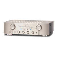
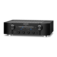
| Product color | Black |
| Channels quantity | 2 channels |
| Connectivity technology | Wired |
| AC input voltage | 120 V |
| AC input frequency | 60 Hz |
| Power consumption (standby) | 0.2 W |
| Power consumption (typical) | 220 W |
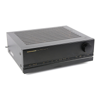
| Depth | 379 mm |
|---|---|
| Width | 440 mm |
| Height | 128 mm |
| Weight | 12000 g |