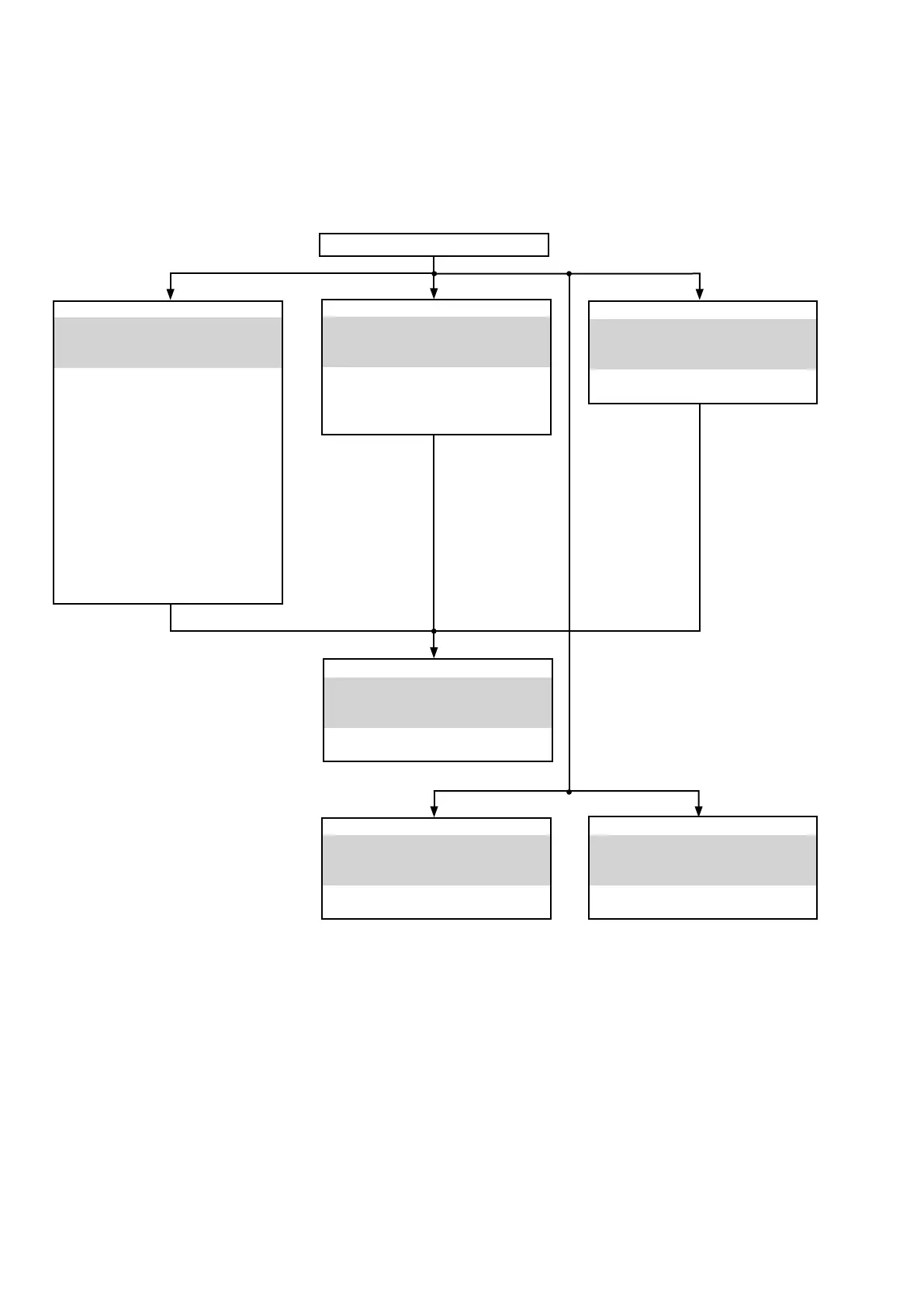
FRONT PANEL ASSY
See
"DISASSEMBLY
1. FRONT PANEL ASSY"
and
"EXPLODED VIEW"
u-COM PCB (110151-1)
(Ref. No. of EXPLODED VIEW : P4)
STANDBY LED PCB (110151-2)
(Ref. No. of EXPLODED VIEW : P5)
INPUT SEL PCB (110151-3)
(Ref. No. of EXPLODED VIEW : P6)
TONE PCB (110151-4)
(Ref. No. of EXPLODED VIEW : P7)
HEADPHONE PCB (110151-5)
(Ref. No. of EXPLODED VIEW : P8)
POWER SW PCB (110151-7)
(Ref. No. of EXPLODED VIEW : P10)
VOLUME PCB (110152-3)
(Ref. No. of EXPLODED VIEW : P14)
REAR PANEL ASSY
See
"DISASSEMBLY
5. REAR PANEL ASSY"
and
"EXPLODED VIEW"
SPK TERMINAL PCB (110152-2)
(Ref. No. of EXPLODED VIEW : P13)
MAIN PCB
See
"DISASSEMBLY
6. MAIN PCB"
and
"EXPLODED VIEW"
MAIN PCB (110150-1)
(Ref. No. of EXPLODED VIEW : P1)
PHONO AMP PCB
See
"DISASSEMBLY
3. PHONO AMP PCB"
and
"EXPLODED VIEW"
PHONO AMP PCB (110152-1)
(Ref. No. of EXPLODED VIEW : P12)
HEAT SINK ASSY
See
"DISASSEMBLY
2. HEAT SINK ASSY"
and
"EXPLODED VIEW"
POWER STAGE PCB (110150-2)
(Ref. No. of EXPLODED VIEW : P2)
CLAMP PCB (110151-6)
(Ref. No. of EXPLODED VIEW : P9)
STANDBY PCB
See
"DISASSEMBLY
4. STANDBY PCB"
and
"EXPLODED VIEW"
STANDBY PCB (110151-8)
(Ref. No. of EXPLODED VIEW : P11)
TOP COVER
DISASSEMBLY
• Disassemble in order of the arrow in the following gure.
• In the case of the re-assembling, assemble it in order of the reverse of the following ow.
• In the case of the re-assembling, observe "attention of assembling".
• If wire bundles are untied or moved to perform adjustment or replace parts etc., be sure to rearrange them neatly as
they were originally bundled or placed afterward.
Otherwise, incorrect arrangement can be a cause of noise generation.
10